


22
3. Power factor improvement
Booster coil reactor and PFC rectify AC to DC and control its voltage.
In the motor drive system of sine wave control, power factor can be improved by reducing harmonics. PFC and reactor stabi-
lize the voltage of DC supplied to inverter circuit and make its waveform smooth.
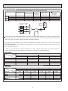
4. Power transistor module
IPM consists of the following components.
· Power Transistors (x6) : Converts DC waveform to three-phase AC waveform and outputs it.
· Drive Circuit : Drives transistors.
· Protection circuit : Protects transistors from over current.
Since the above components are all integrated in IPM, IPM has a merit that can get the control circuit simplifi ed and miniatur-
ized.
5. Elimination of electrical noise
NOISE FILTER CIRCUIT, which is formed by *CMC COILS and capacitors placed on the noise fi lter P.C. board, eliminates
electrical noise of AC power that is supplied to main power supply circuit. In short, common mode noise is absorbed in this
circuit.
Moreover, normal mode noise is absorbed in another NOISE FILTER CIRCUIT which is formed by *NMC COILS and capaci-
tors.
Both NOISE FILTER CIRCUIT exists for preventing the electrical noise generated in the inverter circuit from leaking out.
*CMC COILS; Common mode choke coils
*NMC COILS; Normal mode choke coils
3-1-3. Sine wave control
In these air conditioners, compressor equips brushless DC motor which doesn't have Hall element.
In short, the motor is sensorless. However, it's necessary to locate the polar direction of rotor in order to drive brushless DC mo-
tor effi ciently. The general detection method of the polar direction for such a DC motor is to locate it from the voltage induced by
unenergized stator.
Therefore, it is necessary to have a certain period of time in which the stator is being unenergized for the rotor position detection
when the voltage of supplied power is impressed.
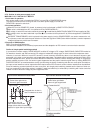
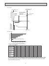
So the motor has been driven by square wave control (the conventional motor drive system) which energizes the motor only
when the range of electrical angle is within 120° because it is forced to be unenergized within 30° at start & end of one heap in
one waveform cycle (180°) when the voltage is impressed.
However, torque pulsation occurs at rotation in this method when the current-carrying phases are switched over to other phases
in sequence. Therefore, sine wave control system is adopted for these air conditioners because it can make the phase-to-phase
current waveform smoother (sine wave) in order to drive the motor more effi ciently and smoothly.
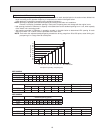
3-1-4. Characteristics of sine wave control in case of brushless DC motor
●
Although ordinary three-phase induction motor requires energy to excite the magnetic fi eld of rotor, brushless DC motor
doesn't need it. So, higher effi ciency and torque are provided.
●
This control provides the most effi cient waveform corresponding to the rotation times of compressor motor.
●
The rotation can be set to higher compared to the conventional motor drive system. So, the time in which air conditioner can
be operated with energy saved is longer than conventional models. This can save annual electric consumption.
●
Compared to square wave control, the torque pulsation is reduced at rotation so that the motor operates more quietly.
●
Since response and effi ciency are enhanced in sine wave control, fi ner adjustment can be provided.
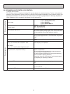
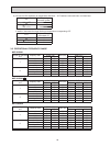
DC Motor AC Motor
Rotor Permanent magnet is embedded Excited by magnetic fi eld of stator
Rotor Position Signal Necessary Unnecessary
In brushless DC motor, permanent magnet is embedded in the rotor. Therefore, it doesn't require energy to excite the rotor
like AC motor does. However, it's necessary to control the frequency of three-phase AC current supplied to the stator accord-
ing to the polar direction of magnet embedded in the rotor so as to drive the motor effi ciently. Controlling 3 phase AC current
frequency also means controlling the timing to switch the polarity of stator. Therefore, the polar direction of rotor needs to be
detected.
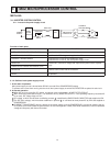
3-1-5. Control Method of Rotation Times
Sine wave control makes the current transformers conduct real time detection of the value of the current running into the mo-
tor, locates the rotor position from the detected value and decides if voltage should be impressed and if frequency should be
changed.
Compared to the conventional control and rotor position detection method, sine wave control can provide fi ner adjustment of the
voltage of supplied power. The value of the current running into the motor is determined by each motor characteristic.