


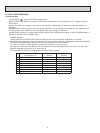
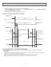
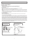

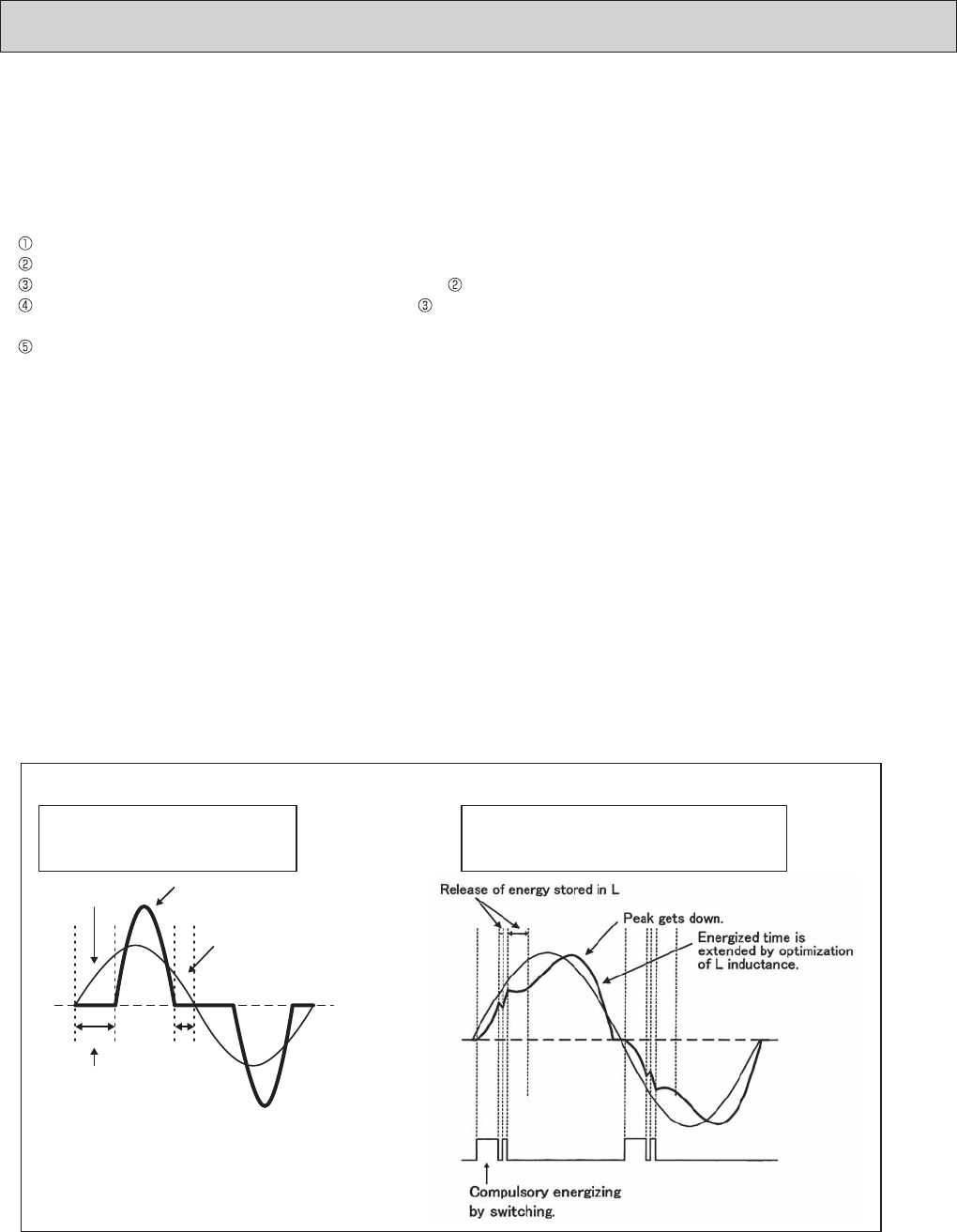
Input current waveform without PAM Input current waveform with PAM
Due to the time of no electricity;
· Power factor gets worse.
· Harmonic gets increased.
Input voltage
Energized time is short in
case L inductance is small.
No electricity runs into
diode module because the
voltage at both sides of smoothing
capacitor is higher than input voltage.
Input current
Owing to the increase of energized time;
· Power factor gets better.
· Harmonic gets suppressed.
14
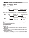
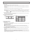
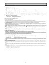
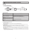
2-7-2. Outline of main power supply circuit
MUZ-A09/12/15/17 MUY-A15/17 MUZ-FD
1. At the start of operation
Main power supply circuit is formed when RELAY is turned ON at COMPRESSOR startup.
To prevent rush current from running into the circuit when power supply is turned ON,
RESISTOR is placed in sub circuit.
2. At normal operation
When AC runs into POWER P.C. board, its external noise is eliminated in NOISE FILTER CIRCUIT.
After noise is eliminated from AC, it is rectifi ed to DC by DIODE MODULE 1.
DC voltage, to which AC has been rectifi ed by process , is stabilized by SMOOTHING CAPACITOR and supplied to IPM.
DC voltage, which has been stabilized in process , is converted to three-phase AC by IPM and supplied to COMPRES-
SOR.
CURRENT TRANSFORMER, which is placed in the power supply circuit to COMPRESSOR, are used to measure the val-
ue of phase current and locate the polar direction of rotor with algorithm. PWM (Pulse width modulation) controls impressed
voltage and frequency with those information.
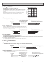
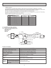
3. Purpose of PAM adoption
PAM : Pulse Amplitude Modulation
PAM has been adopted for the effi ciency improvement and the adaptation to IEC harmonic current emission standard
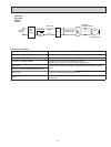
Outline of simple partial switching method
In conventional inverter models, DIODE MODULE rectifi es AC voltage to DC voltage, SMOOTHING CAPACITOR makes its
DC waveform smooth, and IPM converts its DC voltage to imitated AC voltage again in order to drive the compressor motor.
However, it has been difficult to meet IEC harmonic current emission standard by above circuit because harmonic gets
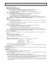
generated in the input current waveform and power factor gets down. The simple partial switching method with PAM, which
has been adopted this time, places and utilizes BOOSTER CHOPPER CIRCUIT before rectifying AC voltage in the general
passive-method converter circuit. As harmonic gets suppressed and the peak of waveform gets lower by adding BOOSTER
CHOPPER CIRCUIT as mentioned above and by synchronizing the timing of switching with the zero-cross point of waveform,
the input current waveform can be improved and the requirement of IEC harmonic current emission standard can be satisfi ed.
Since the switching synchronized with the zero cross point, this simple partial switching method has the feature of lower en-
ergy loss compared to active fi lter method. In addition, output and effi ciency is enhanced by combining with vector-controlled
inverter in order to boost the voltage of power supplied to IPM.