


18
DISASSEMBLY INSTRUCTIONS
9
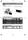
MSH-A18ND MSH-A24ND
INDOOR UNIT
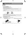
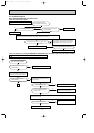
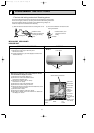
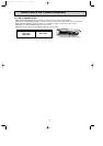
(1) Slide the sleeve and check if there is a locking lever or not.
(2) The terminal with this connector has the
locking mechanism.
1Slide the sleeve.
2Pull the terminal while
pushing the locking
lever.
1Hold the sleeve, and
pull out the terminal
slowly.
The terminal which has the locking mechanism can be detached as shown below.
There are two types ( Refer to (1) and (2)) of the terminal with locking mechanism.
The terminal without locking mechanism can be detached by pulling it out.
Check the shape of the terminal before detaching.
<"Terminal with locking mechanism" Detaching points>
Connector
Sleeve
Locking lever
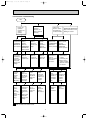
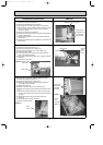
OPERATING PROCEDURE PHOTOS
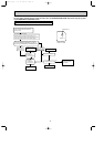
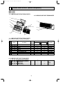
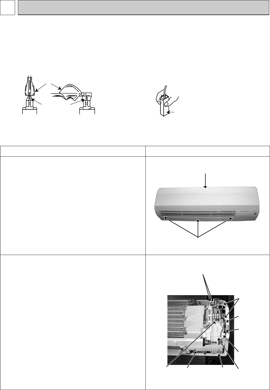
1. Removing the front panel
(1) Remove the screw caps of the front panel.
Remove the screws.
(2) Pull the panel down to your side slightly and unhook the
catches at the top.
Photo 1
Photo 2
Front panel
Screws
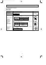
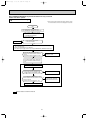
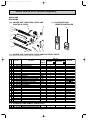
2. Removing the electronic control P.C. board, the receiver
P.C. board and the display P.C. board
(1) Remove the front panel. (Refer to 1.)
(2) Remove the screw of the electrical cover.
Remove the electrical cover.
(3) Remove the screws of the V.A. clamp.
Remove the V.A. clamp.
(4) Remove the screw of the terminal block.
(5) Remove the screws of the ground wire.
(6) Disconnect all the connectors and all the lead wires on the
electronic control P.C. board.
(7) Remove the R.L holder.
(8) Remove the electronic control P.C. board.
(9) Open the R.L holder, remove the receiver P.C. board and
the display P.C. board.
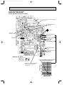
Indoor
electronic
control
P.C.board
Vane motor
connector
Fan motor
connectors
Screws of the ground wire
Screw of
the electrical
cover
Screw of the
V.A. clamp
R.L
holder
Screw of
the terminal
block
Receiver
P.C.
board
OB427B-1.qxp 07.5.16 3:30 PM Page 18