


17
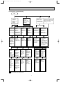
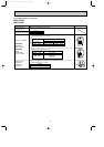
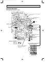
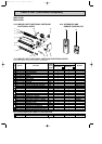
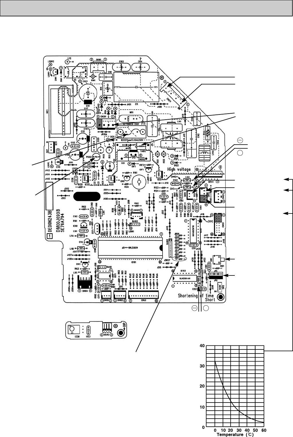
8-6. Test point diagram and voltage
MSH-A18ND MSH-A24ND
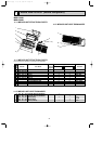
Indoor electronic control P.C. board
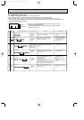
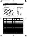
Indoor coil thermistor(RT12(main), RT13(sub))
Room temperature thermistor (RT11)
Resistance(k")
Fan motor power supply
Fuse (F11)
250V AC 3.15A
}
Power supply input
220V AC
+
}
5V DC
Indoor coil
thermistor(RT12(main))
Timer short mode point
(JPS, JPG)
(Refer to 7-1.)
Emergency operation
switch
+
}
12V DC
Room temperature ther-
mistor(RT11)
Release of “Auto restart function”
Solder jumper wire to JR07.
(Refer to 7-3.)
MSH-A24ND
Indoor coil
thermistor(RT13(sub))
PS132
Receiver P.C. board
OB427B-1.qxp 07.5.16 3:30 PM Page 17