52
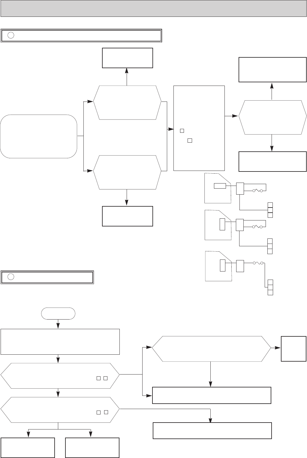
Check both “parts side”and “pattern
side”of indoor electronic control P.C.
board visually.
Check of indoor electronic control P.C. board
C
The unit doesn’t operate with the
remote controller.
Also, the OPERATION INDICA-
TOR lamp doesn’t light up by
pressing the EMERGENCY
OPERATION switch.
Be sure to check both fuse
and varistor in any case.
Replace the fuse.
1.Pull out power supply
cord.
2.Measure resistance
between CN201
on indoor electronic
control P.C. board
and on the terminal
block with a tester.
Trouble of indoor electronic con-
trol P.C. board.
Is there resistance ?
(Approx.0Ω)
Trouble of fuse(F12)
Replace the varistor.
1
N
Yes
No
Yes
No
No
Is varistor(NR11)burnt?
Yes
Is fuse(F11)blown?
Check of outdoor unit
D
Compressor and outdoor fan do not operate.(Only indoor fan operates.)
Start
Press EMERGENCY OPERATION switch.
3-minute time delay works.
Test run operation operates for 30 minutes.
Check voltage to terminal block of outdoor unit. Is
there AC220-240V to terminal block between - ?
Check voltage to terminal block of indoor unit. Is
there AC220-240V to terminal block between - ?
Check the outdoor DEICER P.C.board at first, then check
the outdoor fan motor and the compressor.
Check the continuity of indoor and outdoor unit connection.
2
N
2
N
No
No
Yes
Yes
L
N
Terminal
block
CN201
1133
07/09NV
12/18NV
11
22
L
N
Terminal
block
CN201
F12
F12
Is voltage applied to fan motor and compressor
relay normal when you look at checkpoints about
outdoor DEICER P.C.borad?
Replace
DEICER
P.C.board
No
24NV
07/09/12/18NV
Yes
Confirm wiring connection
at indoor terminal block.
Replace the indoor elec-
tronic control P.C. board.
07/09/12/18NV
24NV
24NV
11
33
L
N
Terminal
block
CN201
F12
23
NF
OB207t-2qxp 25/9/97 8:56 PM Page 52


