


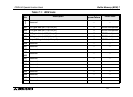
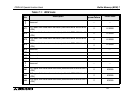
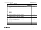
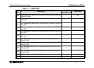

Buffer Memory (BFM) 7
7-1
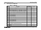
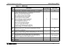
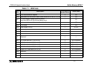
7. Buffer Memory (BFM)
Caution
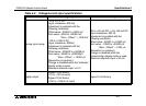
1) Do not access the “Reserved” buffer memories “Reserved” (BFM #16, #17, #24, #31 to
#40, #46 to #50, #56 to #70, #75 to #80, #85 to #90, #95 to #98, #100, #110, #120 to
#199) using FROM/TO instructions. Accessing the reserved buffer memories may cause
abnormal behavior in the FX
2N
-5A module.
Data transfer between the FX
2N
-5A and the PLC main unit is performed through buffer
memories (hereafter referred to as "BFM") of the FX
2N
-5A.
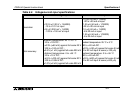
Each BFM consists of 1 word, 16 bits. The BFM No. 0 to 249 and a function are assigned to
each BFM.
Use FROM/TO instructions or direct specification of buffer memory
*1
to read and write data
between the BFM and the PLC.
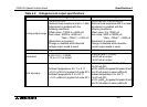
When the power is turned on, the initial value is written to each BFM. When you would like to
use different contents of the BFM, create a program for the PLC so that the desired contents
are written to the BFM every time the power of the PLC is turned on.
(The contents stored in BFM #0, #1, #18, #19, #22, #25, #41 to #45, #51 to #55, #71 to #74,
#81 to #84, #200 to #249 are stored in the built-in EEPROM, and held against power failure.)
*1 This function is supported only in FX
3U
/FX
3UC
PLCs.
FX2N-5A Special function block