


4
5
OPERATION
ASSEMBLY
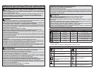
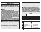
Symbology
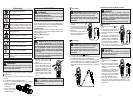
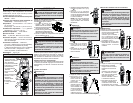
Changing the Batteries
Replace batteries when the low battery indicator
is displayed.
1. Turn rotary dial to OFF and disconnect the test
leads.
2. Unscrew and remove battery door.
3. Insert two (2) AAA batteries, according to the
polarity marked in
the battery com-
partment
4. Close the battery
door and tighten
screw securely.
WARNING
To avoid an electrical hazard, turn the rotary
dial to OFF and disconnect the test leads
before replacing batteries.
Read Operator’s Manual
Double Insulation
Risk of Electric Shock
Indicates that this instrument can
clamp on bare conductors when mea-
suring a voltage corresponding to the
applicable measurement category,
which is marked next to this symbol.
Earth (Ground)
Danger, Warning, or Caution
Battery
European Conformity Mark
Underwriters Laboratories, Inc.,
United States and Canada
1
Canadian Conformity Mark
Cat III
Classifi cation of transient overvolt-
ages, based on nominal line voltage
to earth.
DANGER To avoid electrical shock:
Never make measurement on a circuit in
which voltage over 600 volts AC exists. Clamp
tips are designed not to short the circuit under
test. If equipment under test has exposed
conductive parts, however, extra precaution
should be taken to minimize the possibility
of shorting.
Do not use with the battery cover removed.
Disconnect the test leads from the instrument
for current measurement.
Before Use
Confi rm the rotary dial is set to the correct position,
the instrument is set to the correct measurement
mode, and the hold function is disabled. Otherwise,
desired measurement cannot be made.
LCD Backlight
The LCD backlight will turn off after about 10 min-
utes of inactivity. Push the backlight button to turn
the backlight on or off.
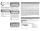
Making a Measurement
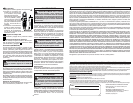
AC Current
WARNING
Only use MILWAUKEE test leads with the
MILWAUKEE Clamp Meter.
Inspect test leads before each use. Use Clamp
Meter to run a continuity test.
1. Set the rotary dial to
position. AC mark is dis-
played.
2. Press the jaw opening trig-
ger to open the jaws and
clamp them around the
conductor under test. The
reading is displayed.
NOTE: Do not clamp over 2
or more wires at the same
time. Irregular results will
occur.
CAUTION Maximum conductor size
is 1" diameter. During measurement,
keep the jaws fully closed to ensure accurate
measurements.
200A
DANGER To avoid electrical shock:
Never make measurement on a circuit in
which voltage over 600 volts AC exists.
Do not use with the battery cover removed.
Keep fi ngers away from jaws during mea-
surements.
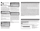
AC Voltage
1. Set the rotary dial to
position.
2. Connect the red test lead
to the V terminal and the
black test lead to the COM
terminal.
3. Connect the test leads to
the circuit under test. The
reading is displayed.
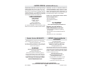
1.5V
1.5V
1. Set the rotary dial to
position.
2. Connect the red test lead to the V terminal and
the black test lead to the COM terminal.
3. Connect the red test lead to the positive (+) side
and black test lead to the negative (-) side of the
circuit under test. The reading is displayed. A
reversed connection is indicated as a negative
value.
DANGER To avoid electrical shock:
Never make measurement on a circuit in
which voltage over 600 volts DC exists.
Do not use with the battery cover removed.
Keep fi ngers away from jaws during mea-
surements.
DC Voltage
DANGER
To reduce the risk of electric shock for
Resistance and Continuity measurements,
never use the meter on an energized circuit.
If testing a capacitor, make sure it is fully
discharged before touching or attempting to
make a measurement.
Do not use with the battery cover removed.
Resistance
1. Set the rotary dial to
posi-
tion.
2. Connect the red test lead
to the V terminal and the
black test lead to the COM
terminal.
Confi rm “OL” is indicated on
the display, and then touch
the tips of the test leads to-
gether to short circuit them
to confi rm the zero indication.
3. Connect the test leads to
both ends of the resistor
under test. The reading is displayed.
CAUTION
After shorting the test leads, the displayed
value may not be zero due to the resistance
of test leads themselves.
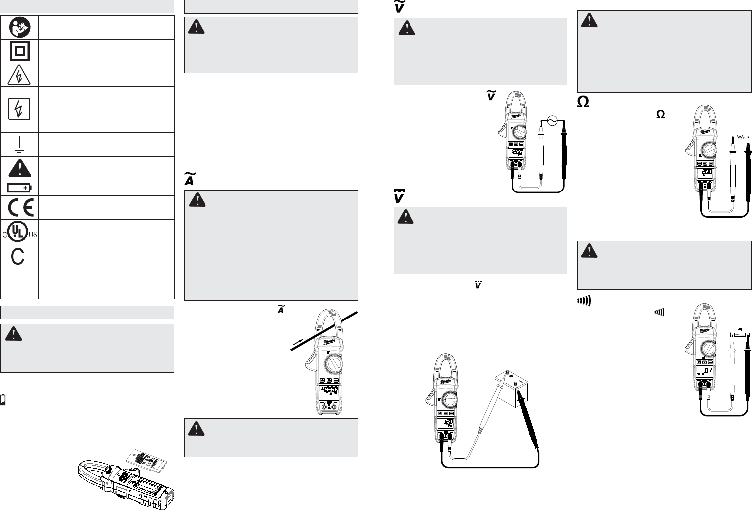
Continuity
1. Set the rotary dial to posi-
tion.
2. Connect the red test lead
to the V terminal and the
black test lead to the COM
terminal.
Confi rm “OL” is indicated on
the display, and then touch
the tips of the test leads to-
gether to short circuit them
to confi rm the zero indica-
tion. A buzzer will sound.
3. Connect the test leads to
both ends of the conductor under test. If the
resistance under test is 30 or less, the buzzer
will sound.
12V
Resistance/Continuity Measurements