


JM-1P OPERATING INSTRUCTIONS
21
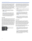
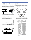
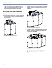
3. Secure the rear GuideALinks with the quick-release pins
stored at the center top and center bottom of the loud-
speaker. The pins can be inserted top down or bottom
up.
4. Face the front of the loudspeakers and position the loud-
speakers so their adjacent front corners are as close as
possible to each other. The previously attached rear
GuideALinks act as a hinge.
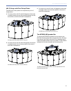
5. Slide the top and bottom front GuideALink knobs to the
right to insert the links into the corner slots of the adja-
cent loudspeaker.
6. Secure the front GuideALinks with the quick-release pins
stored at the right top and right bottom of the loud-
speaker. The pins are inserted from the front.
CAUTION: Routine maintenance inspections
of the JM-1P should include a check of all
GuideALink knobs. Rotate each knob counterclock-
wise to make sure they are tight. If a knob turns, reset
it in the link with Loctite 290 and let it cure for 48
hours. Retest the link before the unit is flown.
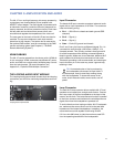
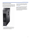
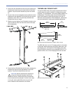
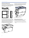
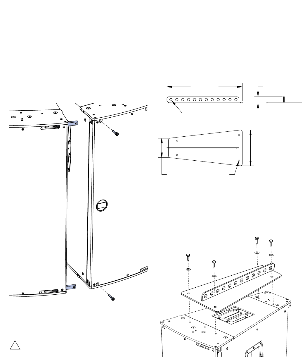
THE MPA-JM1 PICKUP PLATE
The optional MPA-JM1 pickup plate suspends JM-1P hori-
zontal arrays with uptilt or downtilt. A single pickup plate
supports 1–4 loudspeakers. Two pickup plates support 5–6
loudspeakers. The pickup plate comes with M10 knobs,
bolts, and washers for securing the plate to the JM-1P.
Bolts are recommended for fixed installations, while knobs
are recommended for touring and portable applications.
The MPA-JM1 has a row of 12 hanging points in the center
of the plate. When suspending the pickup plate from a sin-
gle hanging point, the location of the hanging point deter-
mines the uptilt or downtilt of the suspended JM-1Ps. For
greater control, two or more hanging points can be used.
!
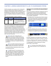
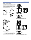
MPA-JM1 Pickup Plate Dimensions; Weight, 16 lbs (7.26 kg)
MPA-JM1 Pickup Plate with JM-1P
23.00
[584 mm]
10.87
[276 mm]
2.00
[51 mm]
Ø0.81 (x12)
[Ø21 mm]
5.95
[151 mm]
Ø0.47 (x4)
[Ø12 mm]