


13
CHAPTER 3: AMPLIFICATION AND AUDIO
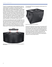
The JM-1P low- and high-frequency drivers are powered by
a proprietary two-channel Meyer Sound amplifier with
MOSFET output stages. The audio signal is processed with
an electronic crossover, correction filters for phase and fre-
quency response, and driver protection circuitry. Each chan-
nel has peak and rms limiters that prevent driver over-
excursion and regulate the temperature of the voice coil.
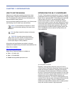
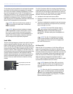
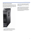
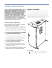
The user panel on the back of the JM-1P has two slots for
modules. The top slot contains an audio input module
(described in this chapter). The bottom slot is reserved for
the optional RMS module, used for connecting to the RMS
remote monitoring system (see Chapter 6, “The RMS
Remote Monitoring System”).
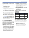
VEAM CABLING
The JM-1P can be ordered from the factory with a VEAM all-
in-one connector. VEAM connectors consolidate AC power,
audio, and RMS into a single cable, facilitating easy connec-
tions and quick setups. For more information, see
Appendix A, “Optional VEAM Multipin Connector.”
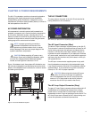
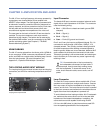
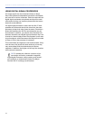
THE LOOPING AUDIO INPUT MODULE
The Looping Audio Input module includes input and looping
connectors, and LEDs for monitoring temperature and limit-
ing.
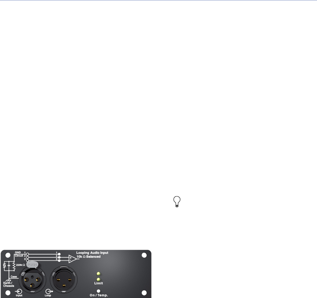
Input Connector
The female XLR Input connector accepts a balanced audio
signal with an input impedance of 10 kOhm. The connector
uses the following wiring:
Pin 1 — 220 kOhm to chassis and earth ground (ESD
clamped)
Pin 2 — Signal (+)
Pin 3 — Signal (–)
Case — Earth (AC) ground and chassis
Pins 2 and 3 carry the input as a differential signal. Pin 1 is
connected to earth through a 220 kOhm, 1000 pF, 15 V
clamped network. This circuitry provides virtual ground lift
for audio frequencies while allowing unwanted signals to
bleed to ground. Make sure to use standard, balanced XLR
audio cables with all three pins connected on both ends.
Telescopic grounding is not recommended, and shorting an
input connector pin to the case may cause a ground loop,
resulting in hum.
TIP: If unwanted noise or hiss is produced by
the loudspeaker, disconnect its input cable. If
the noise stops, there is most likely nothing wrong
with the loudspeaker. To locate the source of the
noise, check the audio cable, source audio, and AC
power.
Loop Connector
The male XLR Loop connector allows multiple JM-1P loud-
speakers to be looped from a single audio source. Connect
the Loop output of the first loudspeaker to the Input of the
second, and so forth. The Loop connector is wired in parallel
to the Input connector and transmits the unbuffered source
signal even when the loudspeaker is powered off.
To avoid distortion when looping multiple JM-1P loudspeak-
ers, make sure the source device can drive the total load
impedance of the looped loudspeakers. In addition, the
source device must be capable of delivering 20 dBV
(10 V rms into 600 ohms) to yield the maximum peak SPL
over the operating bandwidth of the loudspeaker.
Looping Audio Input Module