


3200 & 4200 Series -- 60 --
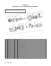
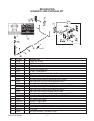
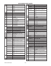
GATE
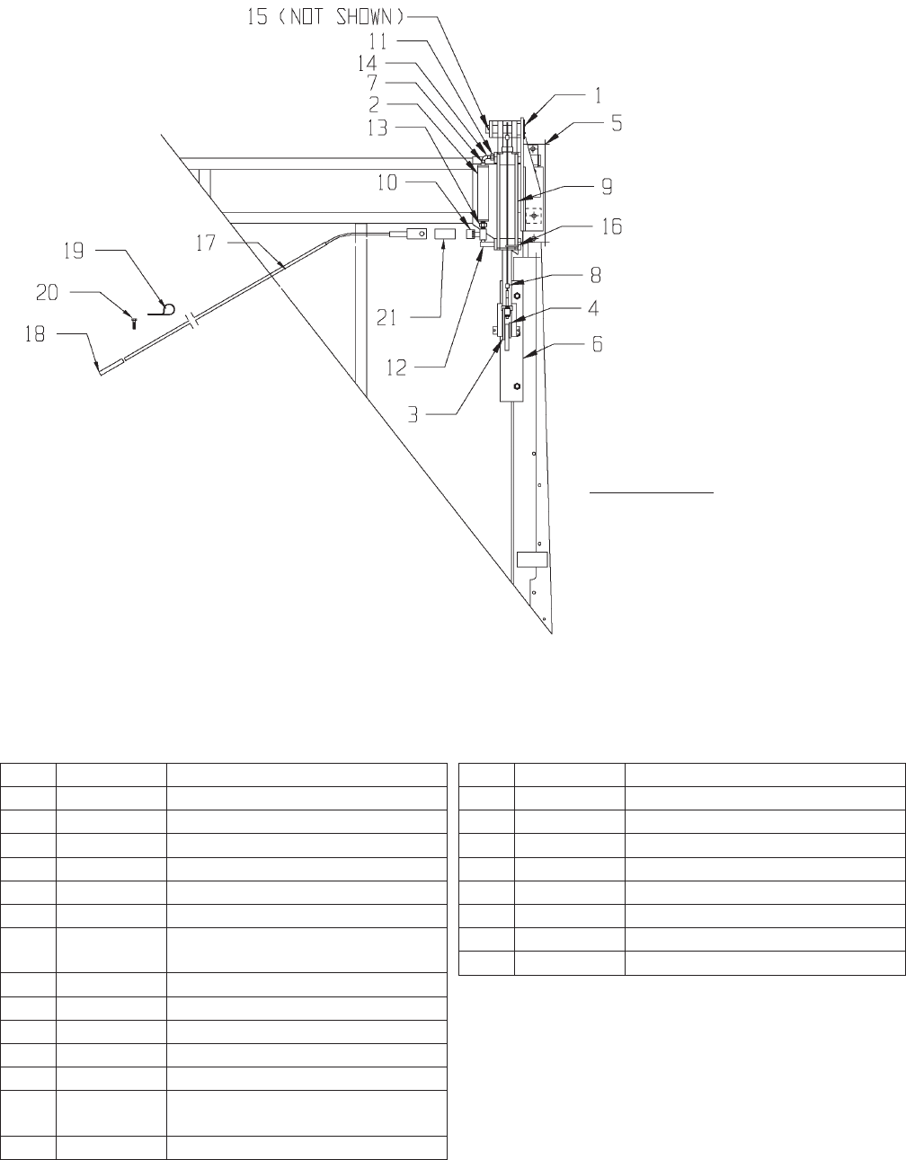
3100/3200/4100/4200 BOX
KEY PART NO. DESCRIPTION
4200-GATE Gate Delay Closing Option
1 25-8092-1 Gate Regulator Top Shaft
2 25-8095 Oil Reservoir Assembly
3 25-8096 Gate Release Trip Arm Assembly
4 25-8097-1 Lower Sleeve Spacer
5 25-8099 Top Cylinder Bracket
6 25-8100 Lower Mount Plate Welded As
-
sembly
7 30-0015 1/4” Fitting x 90 Degree Elbow
8 25-8098 Cable Eyebolt Assembly
9 55-0093 Hydraulic Cylinder
10 55-0094 Flow Control
11 55-0095 1/8” to 3/8” NPT Reducer
12 55-0096 3/8” NPTF x 90 Degree Male Pipe
Elbow
13 55-0097 3/8” to 3/8” Nipple
KEY PART NO. DESCRIPTION
14 735-.25CT 1/4” Copper Tubing (.25 Ft. Req)
15 823-19-2 3/16 x 2” Cotter Pin
16 952-0001-7 Nylon Tie Strap
17 25-8101 Ground Control Rod Assy. W/Grip
18 51-0007 Handle Grip
19 933-3804 5/16 x 4” Eyebolt
20 825-25-1Z 1/4x1" Self Tapping Screw
21 25-8102-2 Drag Sleeve (Hose)
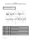
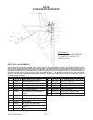
GATE DELAY ADJUSTMENTS
When the gate is completely closed (Tight to rear upright) cable and eyebolt assembly should be adjusted so cable
has no slack. Cable should be tight but not overtightened. If cable and eyebolt is overtightened lower cylinder will trip
out of the L-shaped slot on the lower bracket too soon and the gate will try toclose before the cylinder is stroked out. If
the cable and eyebolt is too loose the lower cylinder will not trip out of the L-shaped slot and the cylinder will reach its
maximum stroke and the gate will still not be in the closed position. The gate will be held open by the top cylinder
bracket and the bracket may become damaged over time. Eyebolt and cable will need to be adjusted periodically to
maintain proper operation.
OIL CAPACITY
WITH 6” OF RAM ROD SHOWING
FILL TANK TO TOP WITH LITE
HYDRAULIC OIL.