


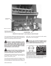
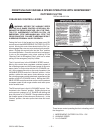
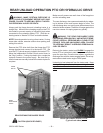
UNLOADING THE FORAGE BOX
Pull the forage box into position and park so that the
cross conveyor discharge opening is in alignment with
the silo filling blower hopper. If the forage box is
equipped with a fold down cross conveyor extension, it
can be lowered before pullingin front ofthe blower. After
a couple of parking trails, you may become familiar with
the correct parking place and be able to lower the cross
conveyor extension after parking. Always park the for
-
age box and unloading tractor in a straight line. Minimize
the unloading angle on the PTO drive shaft to prevent
wearing of universal joints when connected to the un
-
loading tractor PTO. Shift the unloading tractor to “Neu
-
tral” or “Park” and set the brakes.
NOTE: Normal operation is using a farm tractor. If using
some other vehicle, exercise equivalent caution when
parking and exiting this vehicle.
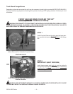
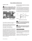
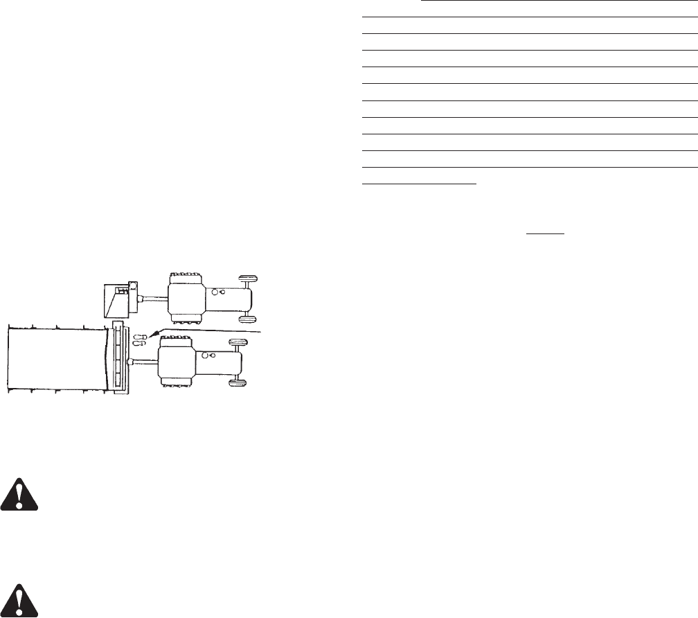
Properly dismount from the tractor and approach the for
-
age box by walking along the left side of the tractor as
shown in the following diagram. Do not approach the for
-
age box from the right side of the machine (left hand un-
load). Approach the left front area of the forage box, as
this is where the control levers are located. Standing in
the operator position will not require crossing the PTO
drive shaft at any time during the unloading operation.
WARNING: DO NOT STEP OVER THE PTO
DRIVE SHAFT. STAY WELL CLEAR OF THE PTO AT
ALL TIMES. FAILURE TO HEED MAY RESULT IN SE
-
RIOUS PERSONAL INJURY OR DEATH.
WARNING: DO NOT STEP UP ON ANY PART
OF THE FORAGE BOX AT ANY TIME. FAILURE TO
HEED MAY RESULT IN SERIOUS PERSONAL IN
-
JURY OR DEATH.
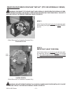
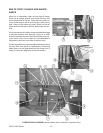
START UP PROCEDURES
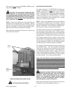
Remove PTO drive shaft from the forage box PTO stor
-
age bracket and connect to the tractor PTO. Be sure the
PTO yoke is securely locked to the tractor PTO. If using
an optional hydraulic drive,couple the hydraulic hoses to
the power supply.
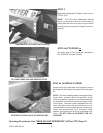
Check that the INDEPENDENT OUTFEED CLUTCH
control lever is in the “Stop” position and the VARIABLE
SPEED & HI-LO RANGE control levers are in the “Neu
-
tral” positions.
NOTE: The INDEPENDENT OUTFEED CLUTCH,
VARIABLE SPEED, and HI-LO RANGE control levers
must be in their “Stop” or “Neutral” positions when en
-
gaging and disengaging the PTO drive shaft (or optional
hydraulic drive). All forage box control lever selections
are to be made while the PTO (or hydraulic) power is in
operation. If the control levers are engaged before
power is applied, damage may occur to the Variable
Speed drive or Independent Outfeed Clutch drive or
both. Failure to follow correct operating procedures
may cause equipment damage and may void the manu-
facturers warranty.
At this time, start the silo filling blower. Return to the for-
age box unloading tractor, slowly
engage the PTO, and
set the engine speed from 1300-1500 rpm.to give a PTO
speed of 300-375 rpm.
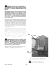
Return to the operator’s position adjacent to the forage
box controls. Intermittently engage the INDEPENDENT
OUTFEED CLUTCH control lever to the “Run” position
and allow the cross conveyor to empty out any accumula
-
tion of forage in the front unloading unit. After the forage
has emptied, fully engage the INDEPENDENT
OUTFEED CLUTCH controllever into the “Run”position.
Next, engage the VARIABLE SPEED control lever to
clear forage from the three unloading augers. Intermit
-
tently move the lever between “Neutral” and the 1
st
and/or 2
nd
notch settings on the control quadrant. This
will engage and disengage theaugers at aslow speedto
clear them without the main apron moving forward; be
-
cause the HI-LORANGE control lever isstill in “Neutral.”
With the augers cleared and running and the VARIABLE
SPEED control lever in a slow speed setting, move the
RANGE control lever to “LO” and the main apron chain
will begin to move forward. Moving the VARIABLE
SPEED control lever down on the control quadrant will
increase speed of both auger rotation and main apron
forward travel. Keep increasing speedof the VARIABLE
SPEED control to regulate rate of forage box unloading
speed to match the capacity of the silo filling blower.
3200 & 4200 Series -- 16 –
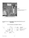
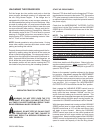
OPERATOR TRAFFIC PATTERN
LH Side
OPERATOR
POSITION
RH Side