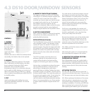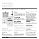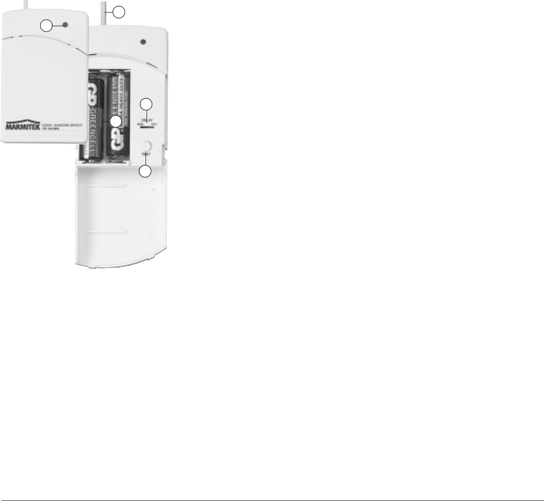
CONTROLS:
1. CONTROL
INDICATOR
When you press
the button TEST, or
when the unit is
transmitting a
signal to the base
station, this
indicator will come on. When the indicator blinks
only weakly, the batteries have to be replaced.
2. MIN/MAX
For setting a delay time of approx. 30 seconds.
When switched to the MAX position, the delay
time is activated. Position the DELAY switch
behind the cover to the MIN position
(instantaneous alarm). For an entrance door you
set the switch to MAX, allowing you to enter and
disarm the system When you want e.g. a garden
door to respond immediately, you switch the DS10
to the MIN position.
3. TEST
Used for activating and installing the sensor
during the installation procedure. Can also be
used to test the sensor.
4. MAGNETIC CONTACTS (NOT SHOWN)
The magnetic contacts are of the NC (Normally
Closed) type. The distance between magnet and
contact can not be more than 5mm. When
mounted, you have to make sure that the arrows
on magnet and contact line up. The length of
wire between contact and sensor can be
expanded or shortened. Make sure that the wires
are well connected and the screws tightened.
Multiple magnet switches can be placed in series.
5. BATTERY COMPARTMENT
Place 2 pieces AA batteries observing the polarity
instructions in the battery compartment. Use
preferably alkaline batteries.
INSTALLATION (install mode):
The Door/Window Sensor consists of a transmitter
and a magnetic contact. The magnetic contact
consists of 2 parts: the wired NC contact and a
separate magnet. Normally the magnet will make
the contact to close. When opening of a door or
window, the contact be opened and a message
will be sent to the base station (the red indicator
will come on).
The DS10 is primarily meant for doors and
windows, whereby the transmitter part and
contact will be placed on the frame and the
magnet on the moving part (door or window).
Look on door or window frame where the sensor
can be positioned without running the risk of
obstructing or damaging the sensor when
opening this door or window. Position the sensor,
if possible, as high up as possible. This will result in
the best possible range. Then mark the position of
the sensor and magnet contact. Do not place the
magnet contact directly on a metal surface. In
case of a metal or metal enforced plastic window-
frame, it is recommended to use a 5mm wooden
or plastic isolator between magnet contact and
frame.
For metal frames, the distance between contact
and magnet can not be more than 3mm when
door or window is in closed position. For wooden
frames this distance is 8mm, but in all cases the
opening should be kept to the minimum. To
mount the transmitter part, you remove the
batteries and screw the back of the transmitter
onto a suitable background.
For lift-up or sash windows, the contact and
magnet should NOT slide along each other, but
should be positioned in such a way that they
clearly move away from each other.
Remove the protective cover of the double-sided
tape on the magnet and position this on the
opening part of window or door. Remove the
protective cover of the double-sided tape on the
contact and position this on the frame.
N.B.: Make sure that the arrows on the contact
and magnet line up.
After testing the system, it is recommended to
also screw down the magnet on the surface.
6. MOUNTING THE ANTENNA OF EXTRA
DOOR/WINDOW SENSORS
Extra door/window sensors are supplied with a
wire antenna and a separate antenna tube. For
proper operation, slide the plastic tube over the
antenna wire and push it firmly into the sensor
housing.
ACTIVATING THE DS10
Push the TEST key of the DS10 for more than 1
second; the indicator blinks twice. Then press the
TEST key once more and close the battery cover.
N.B.: When replacing the batteries of the sensor
when the system is operational, you can make
sure that the sensor maintains its unique code
avoiding re-installation. To do this, you OPEN the
door or window that is protected by this sensor.
After replacing the batteries, you can close the
8 MARMITEK
4.3 DS10 DOOR/WINDOW SENSORS
1
5
6
2
3


