


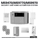


7MS9470/MS9770/MS9970
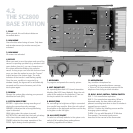
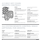
13. ENTER
Used for confirmation of the system settings
during installation.
14. TIME OFF
Used to set the Lifestyle mode. When pressing this
key at a certain time, the Lifestyle program will be
switched off every day at that specific time (refer
to 6.9).
15. RECORD
Used for recording and replaying of the alarm
message during installation.
16. ZONE 9-16
Used for switching from zone-indicators 1-8 to
9-16.
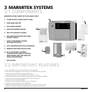
17. ZONE-INDICATORS
These indicators give the status of each installed
zone. Each zone represents one sensor.
18. WIRED SENSOR/EARPHONE JACK
This input jack has two functions:
You can listen to the recorded alarm message
during installation.
A wired sensor can be connected to this input
(refer to 4.8).
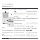
19. SIREN
In case of an alarm this siren gives a piercing
warning signal with a 95dB sound pressure level.
The siren can be switched of if required (silent
alarm). The system allows control of multiple
sirens over regular power lines.
N.B.: Volume and tone can be damaging for your
hearing when you are too close to the siren when
activated.
20. BATTERY COMPARTMENT
This compartment holds the 9 V back-up battery.
This battery keeps the system fully operation in case
of mains power failure. All setting will remain in
memory because these are store in an non volatile
(EEPROM) memory. Use preferably an alkaline
battery (no rechargeable battery). When you are
disconnecting the system on purpose for a longer
period of time, you must disconnect this battery to
avoid unnecessary discharge of this battery.
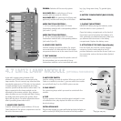
21. TELEPHONE CONNECTION
For connecting the system to the telephone line
(meant for analog lines; for ISDN and PABX, refer
to 4.1). Always use the supplied cable.
22. CONNECTION MAINS ADAPTOR
Connect the supplied PS500 Mains Adapter. Use
only the supplied PS500.
23. ANTENNA
Used for reception of radio signals of sensors and
remote controls. Can be mounted horizontally
(tabletop use) or vertically (wall mounted).
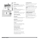
INSTALLATION:
Choose a suitable place for the base station, close
to a power outlet. (230VAC) and a telephone
socket.
For maximising the range, it is recommended to
place the base station as much as possible in the
middle of the premises you want to protect. By
doing this you use the smallest possible distance
between sensors and base station and optimise
the range of the system.
In doing so you have to keep in mind:
1. Avoid placing the base station close to large
metal objects (heater, cooker, etc.)
2. That the place is easy to reach
3.
The base station is not placed close to a PC or TV.
TABLE TOP USE
You can position the base station on any flat
surface (table, console, etc.) or use the bracket for
wall mounting. The rubber feet make sure that
the base station remains in its position.
WALL MOUNTING
The supplied wall-mounting bracket allows you to
install the SC2800 base station vertically against a
wall. Mount the SC2800 at such a height that you
can view and operate the panel easily.
For wall mounting, you have to install the radio
antenna in the vertical position. Carefully pull the
plastic tube away from the antenna wire. Then
pull the antenna wire through the vertical-
mounting hole and reposition the plastic tube
over the antenna wire.
CONNECTING THE PS500 MAINS ADAPTER
Connect the DIN plug into the socket at the back
of the base station. Plug the mains adapter PS500
into a 230 V wall outlet.
PLACING OF THE BACK-UP BATTERY
Open the battery compartment at the back of the
base station. Connect the 9 V block battery
observing the correct polarity. Place the battery in
the compartment and close the battery cover.
N.B: The back-up battery has a limited capacity,
which will be used as soon as PS500 mains
adapter does not supply the base station
anymore. Be aware of this when disconnecting
the PS500 on purpose.
CONNECTING TELEPHONE CABLE
Connect the supplied telephone cable to the back
of the base station. Connect the telephone plug
in your telephone wall socket. (refer to 4.1 for
more information on ISDN and PABX connection).