


NOTE: DIAGRAMS & ILLUSTRATIONS NOT TO SCALE.
8
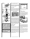
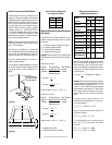
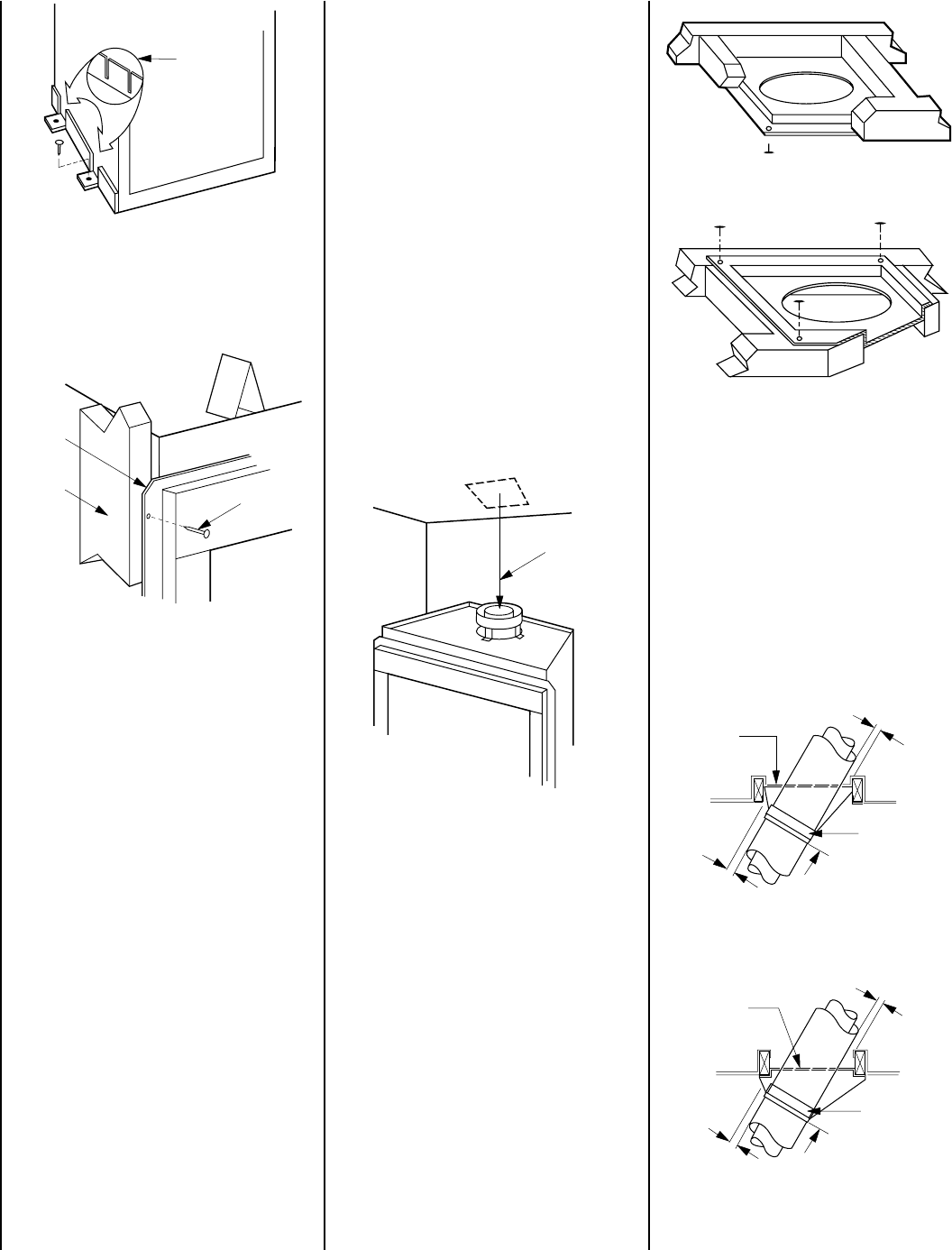
Firestop Spacer
Room Above
Firestop Spacer
Attic Above
F10FS30-2
Firestop Spacer
FTF10-S4
Stabilizer
2" Min.
Air Space
30° Firestop
And Attic Above
10'
Max.
Attic Space
2" Min.
Air Space
F10FS30-2
Firestop Spacer
FTF10-S4
Stabilizer
30° Firestop
And Room Above
10'
Max.
Room Above
2" Min.
Air Space
2" Min.
Air Space
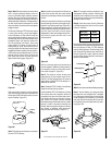
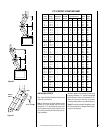
CAUTION: ALLOW MINIMUM 2" CHIMNEY
AIR SPACE TO COMBUSTIBLE FRAMING MEM-
BERS THROUGHOUT VERTICAL OR OFFSET
CHIMNEY INSTALLATION.
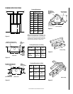
A minimum 2" air space must be reserved for
all combustible materials extending for any
continuous length surrounding the chimney.
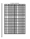
Reference
Figures 15 and 16
and charts Fram-
ing Dimensions for Ceiling and Roof, which
specify minimum ceiling and roof dimensions.
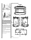
In new construction, to determine chimney cen-
ter line, use plumb line from roof or ceiling above
fireplace to center of flue collar on fireplace.
For remodeling, plumb to center of flue collar
from ceiling above, drive nail through ceiling
from below to mark position, then mark and
cut to passage from above ceiling (around
nail) (
Figure 19
). Then plumb from ceiling or
roof level directly above hole which has just
been completed.
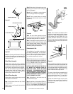
Figure 17
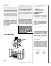
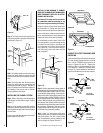
Step 4. The fireplace should be secured to the
side framing members using the nailing flange.
Use 8d nails (
Figure 18
).
Anchor Tab
Nailing
Flange
Framing
Stud
8d Nail
Figure 19
Plumb Line
Figure 21
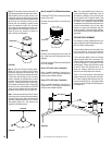
Step 3. Position appropriate firestop spacer at
ceiling and nail temporarily with two (2) 8d nails.
Use flat firestop spacer, Model F10FS-2, if chim-
ney penetrates ceiling vertically. If chimney pen-
etrates ceiling at 30° angle (offset chimney), use
30° firestop spacer, Model F10FS30-2. Use one
nail on opposite sides to hold firestop spacer in
position. Nail permanently, using at least two (2)
more 8d nails, after chimney sections have been
assembled through the firestop spacer and after
any necessary adjustments have been made.
Firestop spacer must be secured by at least four
(4) 8d nails when completely installed.
Note: If there is a room above ceiling level,
firestop spacer must be installed on the bottom
side of the ceiling. If an attic is above ceiling
level, firestop spacer must be installed on top
side of ceiling joist (Figures 20 and 21 ).
Figure 18
Note: The nailing flange and the area directly
behind the nailing flange is exempt from the
clearances described on the fireplace clearance
label.
Note: The nailing tabs and the area directly
behind the nailing tabs are exempt from the
clearances described on page 5. Maintain at
least 1/2" clearance from the firebox wrapper to
the framing at the closest point of contact,
directly adjacent to the flange.
INSTALLING THE CHIMNEY SYSTEM
Step 1. Before continuing, check the operation
of the damper, as described on page 4, (
refer to
Figure 3
).
Step 2. Using standard construction framing
techniques, construct opening for chimney route
up through the ceiling(s) and roof or through an
outside chase.
Framing must maintain adequate minimum air
space clearance at all times.
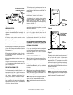
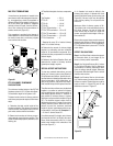
CHIMNEY 30° OFFSET THROUGH FLOOR
OR CEILING
It may be necessary to assemble the chimney at
30° when passing through the floor or ceiling
area. Use the F10FS30-2 firestop spacer as
shown in
Figures 22 and 23
. Support the
chimney at floor or ceiling penetration with a
FTF10 stabilizer if distance of chimney below
ceiling is 10' or more. Maintain 2" minimum air
space to combustibles from chimney sections.
Figure 23
Figure 22
Figure 20