


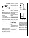
NOTE: DIAGRAMS & ILLUSTRATIONS NOT TO SCALE.
7
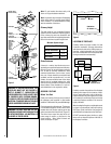
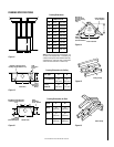
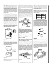
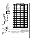
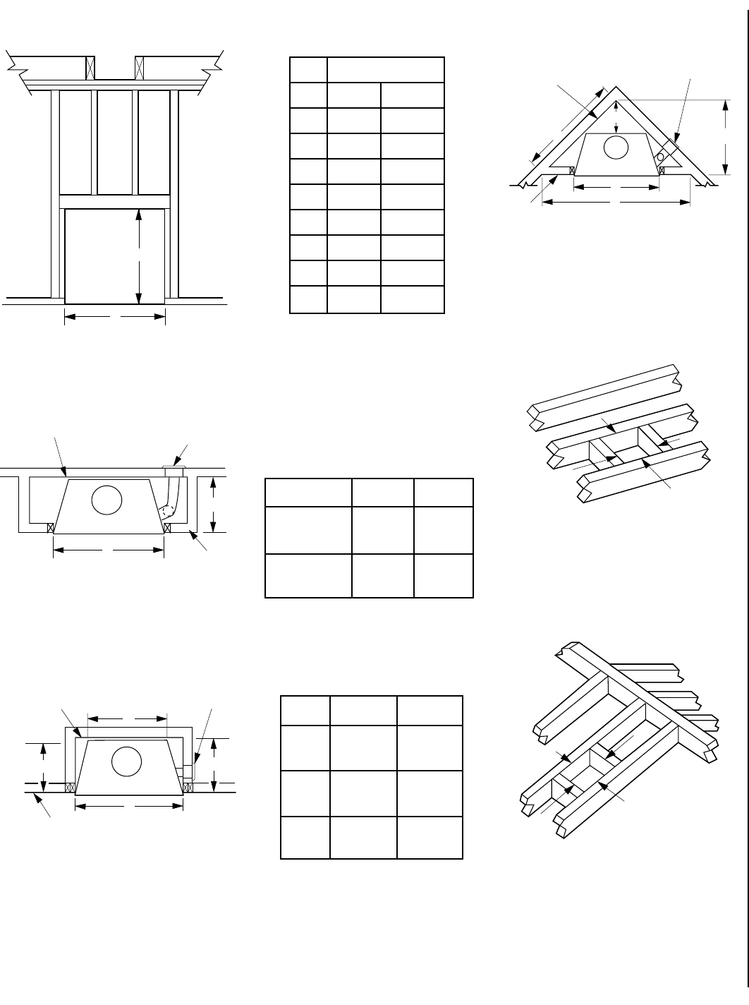
FRAMING SPECIFICATIONS
Figure 11
Figure 12
Framing Dimensions for Ceiling
Flue Type A B
FTF13 Vertical 19" 19"
(483 mm) (483 mm)
FTF13 19" 29"
Offset 30° (483 mm) (737 mm)
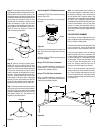
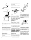
Figure 13
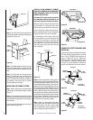
A
Outside Chase
G
C
J
Back Wall of Chase/Enclosure
Including Finising Materials
if any
Rough
Framing Face
(Unfinished Shown)
FOAK
Combustion
Air Kit - Optional
Framing Dimensions for Roof
Pitch C D*
0/12 19" 19"
(483 mm) (483 mm)
6/12 19" 22"
(483 mm) (559 mm)
12/12 19" 27"
(483 mm) (686 mm)
* Perpendicular to roof ridge
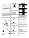
Figure 15
Figure 16
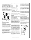
Figure 14
A
B
Ceiling Framing
C
D
Roof Framing
Corner Installation
K
D
A
E
F
Back Wall of
Chase/Enclosure
Including Finising
Materials
if any
Rough
Framing Face
(Unfinished Shown)
FOAK Combustion
Air Kit - Optional
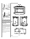
Framing Dimensions
Model EST-48
A 59 ¹⁄₂" 1511 mm
B 53 ³⁄₈" 1346 mm
C 44 ⁄₂" 1130 mm
D 22 ¹⁄₄" 565 mm
E 104" 2641 mm
F 52" 1321 mm
G 29 ³⁄₄" 755 mm
J 31 ³⁄₄" 806 mm
K 73 ¹⁄₂" 1867 mm
Note: All framing dimensions calculated for 1/2"
dry wall at the fireplace face. If sheathing the
chase or finishing with other thickness materials,
calculations will need to be made. False header
should be constructed of 2 x material only.
A
G
Inside Chase
Back Wall of Chase/Enclosure
Including Finising Materials if any
Rough
Framing Face
(Unfinished
Shown)
FOAK
Combustion
Air Kit
A
B