


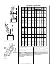


NOTE: DIAGRAMS & ILLUSTRATIONS NOT TO SCALE.
14
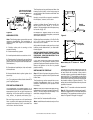
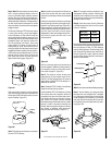
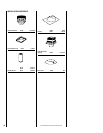
Step 3. Center outer-locking section over outer
chimney pipe. Push down until locking joint
has firmly engaged.
Step 4. Pull up slightly on return elbow to
ensure locking joint has firmly engaged.
Step 5. Secure support straps to framing
members by nailing under tension in sheer
(
Figure 40
).
Return
Elbow
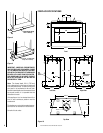
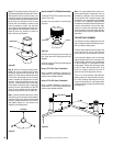
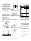
AIR INLET
EYEBROW
ASSEMBLY
FOAK
Figure 41
Figure 42
Figure 40
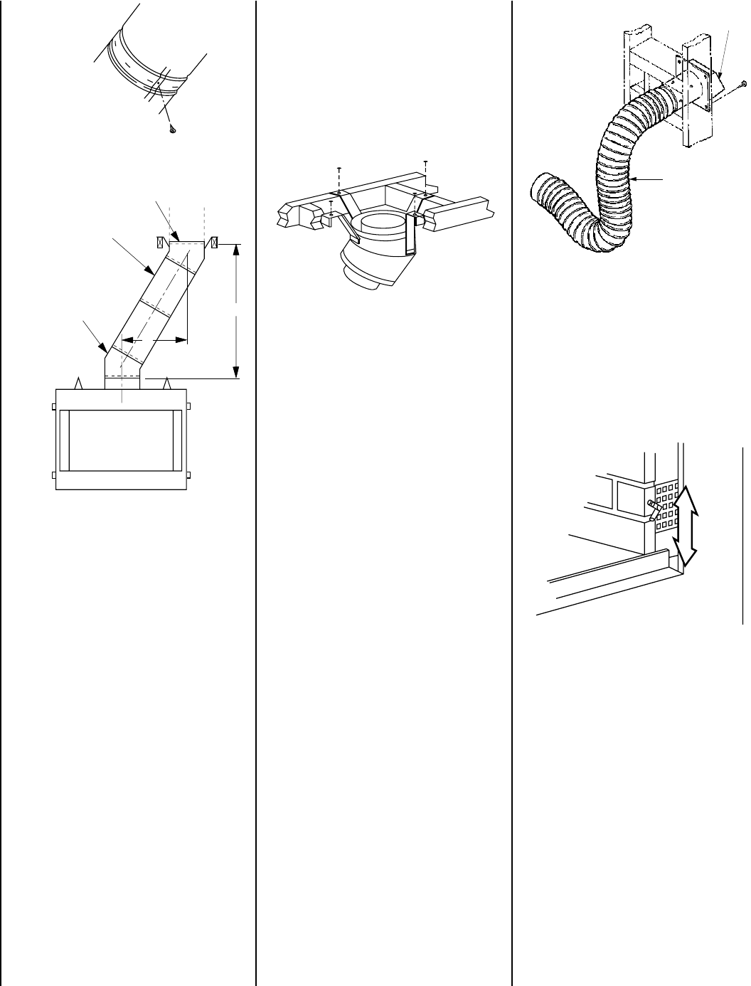
Step 3. The air inlet for the outside air kit is
located on the right hand side of the fireplace
(
Figure 42
). Refer to the installation instruc-
tions packed with each FOAK-4 air kit for
specific installation information. The outside
air kit, if used, must be installed before the
fireplace is totally framed and enclosed within
the finished walls.
Note: The return elbow assembly performs
the same function as a stabilizer. Consider this
when determining the need for a stabilizer.
Note: Do not apply excessive pressure to any
subsequent chimney section following return
elbow assembly when installing. Ensure that
each subsequent chimney section is securely
attached by testing as noted above.
Combustion Air Kits
The installation of an outside combustion air
kit is highly recommended. It is very impor-
tant to ensure good fireplace operation in
homes which are tightly weather sealed or
have ventilating appliances installed.
Step 1. Determine the source for outside air,
which can be installed through an outside wall
or into a ventilated crawl space. In either case,
a 4 1/2" diameter hole will be required for
installation of the air inlet assembly.
CAUTION: AVOID INSTALLING THE AIR IN-
LET WHERE THE OPENING COULD BE
BLOCKED BY SNOW, BUSHES OR OTHER
OBSTACLES. THE MAXIMUM HEIGHT FOR
THE OUTSIDE AIR IS 50 FEET ABOVE THE
HEARTH, PROVING THE AIR INLET IS TERMI-
NATED A MINIMUM OF THREE (3) FEET BE-
LOW THE CHIMNEY CAP LEVEL.
Note: Combustion air inlet ducts must not
terminate in attic space.
Step 2. Install the air inlet eyebrow (FOAK-4 or
FOAK-4LD) through the wall opening (
Figure 41
).
Push a 4 inch diameter NON-COMBUSTIBLE
Class 0 or Class I flexible duct onto the eyebrow.
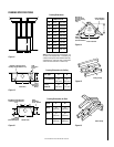
Figure 38
Figure 39
Underside Of Chimney
Note: See Framing and Dimension Chart for
the sizes of the ceiling and roof openings. The
size of the roof opening varies with the degree
of pitch of the roof.
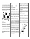
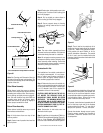
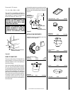
Offset Elbow Assembly
Offset elbows install the same as chimney
sections. First, snap the inner section INTO the
preceding inner section of flue. Check connec-
tion by pulling up slightly to ensure a tight fit.
Next, the outer sections snap lock OVER the
preceding outer section of chimney. Again,
check outer section by pulling up slightly to
ensure proper connection is made.
Return Elbow Assembly
Return elbows install the same way as round
terminations and stabilizers:
Step 1. Hold return elbow over top of last
chimney section.
Step 2. Center inner slip section into inner flue
pipe-slip down.
Chimney Section (S)
FTF13-E30 Return Elbow*
FTF13-30 Offset Elbow*
B
A
*Part of Offset/Return Package Model FTF13-ES30
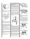
After completing the installation of the optional
combustion air vent system, the actuator arm
must be put in service and tested to ensure
proper operation before completing any enclo-
sure around the firebox. Failure to do so may
result in extensive and costly rework.
To operate, locate the hand operated shut-off
lever at the lower right side of the fireplace
opening behind the screen. To open the air
damper, turn upwards. To close, turn down.
Operate the actuator through several cycles.
Ensuring proper operation and freedom of
movement. Return the actuator arm to the
closed position.
OPEN
CLOSED