


NOTE: DIAGRAMS & ILLUSTRATIONS NOT TO SCALE.
15
OPTIONAL EQUIPMENT
CONSIDERATIONS
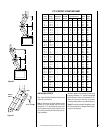
Gas Line Connection
The EST-48 has been listed to accept a ¹⁄₂" gas
line for an approved gas appliance. Always
have the appliance installed in accordance with
all local building codes.
CAUTION: ALL GAS CONNECTIONS SHOULD
ONLY BE PERFORMED BY A QUALIFIED, LI-
CENSED TRADESMAN. THE MAIN GAS SUP-
PLY MUST BE OFF WHEN PLUMBING THE
GAS LINE TO THE FIREPLACE OR WHEN PER-
FORMING SERVICE WORK.
Install a ¹⁄₂" gas supply line through fireplace
wall for connection to a decorative gas appli-
ance inside the firebox. Outside, the gas supply
line connects to a gas shut-off valve recessed
flush into the wall or floor. The valve should be
controlled by a removable valve key for safety.
Always plumb gas line installation per local
codes. Check all connections with soap suds;
leaks will bubble. Never test any gas line con-
nection with a match or open flame.
This provision is intended for connection to a
decorative gas appliance incorporating an au-
tomatic shut-off device and complying with the
Standard for Decorative Gas Appliances for
installation in vented fireplaces, ANSI Z21.60
(1991) or American Gas Association draft re-
quirements for Gas-Fired Log Lighters for Wood
Burning Fireplaces, Draft No. 4 dated August,
1993. Install in accordance with the National
Fuel Gas Code, ANSI Z223.1. This complies
with the revised U.L. 127 standard.
Vent Free Appliances
These units have been tested and approved to
ANSI/IAS/AGA Z21.11.2 for use with unvented
gas appliances and complies with the stan-
dard for Factory-Built fireplaces, UL 127.
The unit has been tested for use with any
unvented gas log sets having a maximum
rating of 40,000 BTU. The minimum mantle
configurations are outlined in
Figure 43
.
These fireplaces have been marked with a
maximum rating of 40,000 BTU to assure that
homeowners do not exceed the allowable lim-
its for all allowed installations of mantles.
NEVER INSTALL AN UNVENTED GAS LOG
SET WITH A BTU GREATER THAN 40,000.
CAUTION: WHEN USING THE DECORATIVE
GAS APPLIANCE, THE FIREPLACE DAMPER
MUST BE SET IN THE FULLY OPEN POSITION.
CAUTION: PLUMBING CONNECTIONS SHOULD
ONLY BE PERFORMED BY A QUALIFIED, LI-
CENSED PLUMBER. MAIN GAS SUPPLY MUST
BE OFF WHEN PLUMBING GAS LINE TO FIRE-
PLACE OR PERFORMING SERVICE.
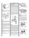
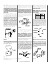
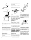
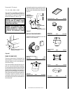
If you’re installing a gas line, connect it before
the fireplace is framed and enclosed in the
finished wall. The gas knockout is determined
by the indentation located at the bottom and
slightly off center in the side refractories. THE
KNOCKOUT IS ALWAYS REMOVED FROM IN-
SIDE THE FIREPLACE. DO NOT REMOVE THE
KNOCKOUT UNLESS YOU ARE INSTALLING A
GAS LINE. If removal is attempted from the
outer wrapper, side refractory damage may
occur. With a medium-sized hammer, lightly
tap the surface of the indentation. The refrac-
tory material is very thin in this area and is easily
removed. Once a small hole has been made,
continue tapping until you have reached suffi-
cient diameter for the gas line to fit through. The
entire knockout does not have to be removed.
Remove insulation in the gas line channel.
IMPORTANT: REPACK INSULATION MATERIAL
IN SQUARE HOLE AROUND GAS LINE, INTE-
RIOR AND EXTERIOR OF FIREPLACE, TO SEAL.
Glass Doors
If glass doors are to be installed on these
fireplaces, refer to specific installation instruc-
tions packed with the glass doors. Use only the
doors that are listed for use with these fire-
places. Use of other non-listed glass door on
these fireplaces may constitute a potential fire
hazard and is not recommended.
CAUTION: CERTAIN GLASS DOORS OVER-
LAP THE BLACK METAL FACING OF THE FIRE-
PLACE. IF THE FIREPLACE HAS BEEN FACED
WITH NONCOMBUSTIBLE MATERIALS,
THERE MIGHT NOT BE SUFFICIENT CLEAR-
ANCE TO INSTALL THE GLASS DOORS OF
YOUR CHOICE. ENSURE ADEQUATE CLEAR-
ANCE IS MAINTAINED AT ALL TIMES SO AS
NOT TO INTERFERE WITH THE INSTALLA-
TION AND OPERATION OF GLASS DOORS.
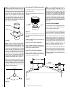
COLD CLIMATE INSULATION
If you live in a cold climate, it is especially
important to seal all cracks around the fire-
place opening with noncombustible material
and wherever cold air could enter the room.
Surrounding materials must be caulked where
it meets the black metal facing of the fireplace
to avoid cold air intrusion. Use noncombus-
tible caulking material only on fireplace facing
to seal. Also, the outside air inlet duct should
be wrapped with noncombustible insulation to
minimize the formation of condensation. Do
not place insulation materials on top of fire-
place or against chimney sections.
Note: A 2" air space must be preserved for all
combustible materials extending for any con-
tinuous length adjacent to the chimney.
It is especially important to insulate between
the studs of an outside chase cavity and under
the floor if the floor is above ground level. Do
not place insulation directly against the fire-
place or chimney system.
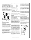
FIREPLACE FINISHES
Mantels and Trim
It is sometimes best to frame your fireplace
after it is positioned and the chimney is in-
stalled. Frame enclosure for chimney and fire-
place with 2 x 4’s (or heavier) lumber.
Note: The header may rest on the two (2) metal
top spacers on top of the unit but the header
must not be notched to fit around the spacers.
These fireplaces may sit directly on a combus-
tible surface. A 2" air space is required be-
tween combustible framing and the chimney.
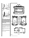
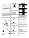
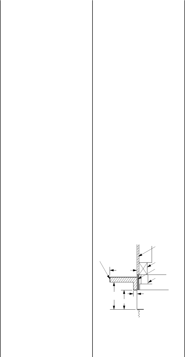
Combustible mantels and trim may be in-
stalled 12" above the fireplace opening as per
NFPA 211, Section 7-2.3.3. and
Figure 43
. If
a mantel is of a noncombustible material, it is
exempt from these requirements as long as it
does not interfere with the installation or op-
eration of glass doors.
Figure 43
8 ⁹⁄₁₆"
1 ¹⁄₂"
12"
Min.
Fireplace
Opening
Spacer
Combustible
Mantel and Trim
12" Max.
Finished
Wall
Typical Installation
Noncombustible
Wall Covering
Header