


7
UVSRC Series Firebox
20002068
Install Gas Log Heater
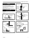
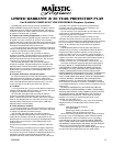
1. Connect a shutoff valve, union and any required
approved fittings (See NOTE below) between the valve
and the gas line.
Access to the gas line on the UVSRC Series firebox is
made through the left or right side of the firebox.
From the inside of the firebox, locate the knockout on
the firebrick - be sure you are on the appropriate or gas
line side of the firebox. Using a flat bladed screwdriver
or small chisel and hammer, carefully tap around the
knockout until it loosens and falls out.
2. Install the Vent-Free Gas Log Heater exactly as
described in the instructions for the heater. If, for any
reason, you do not have these instructions, contact
your dealer or manufacturer for another copy.
NOTE: The gas line connection to the log set can be
made with 3/8" copper tubing approved for propane or
natural gas, 1/2" rigid pipe, or an approved flex connec-
tor. Because some municipalities have additional local
codes, it is always best to consult your local authority.
U.S. INSTALLATIONS — Follow local codes and the
National Fuel Gas Code ANSI Z223.1.
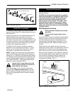
Always check for gas leaks with a mild
soap and water solution. Do not use an
open flame for leak testing.
When using copper or flex connector, use only ap-
proved fittings. Always provide a union so that the
gas line can easily be disconnected for burner or fan
servicing. See gas specifications for pressure details
and ratings.
Electrical Connection
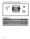
The UVSRC36/42 with optional fan requires 120VAC
electrical hook-up.
CAUTION: All wiring should be done by a qualified
electrician and shall be in compliance with all local,
city and state building codes. Before making the
electrical connection, make sure that the main
power supply is disconnected. The firebox, when
installed, must be electrically grounded in accor-
dance with local codes or, in the absence of local
codes, with the National Electrical Code ANSI/NFPA
70 (latest edition).
EB1 Receptacle Hook-Up
Wiring should be installed by a certified
electrician.
Turn off circuit breaker before wiring
models.
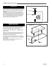
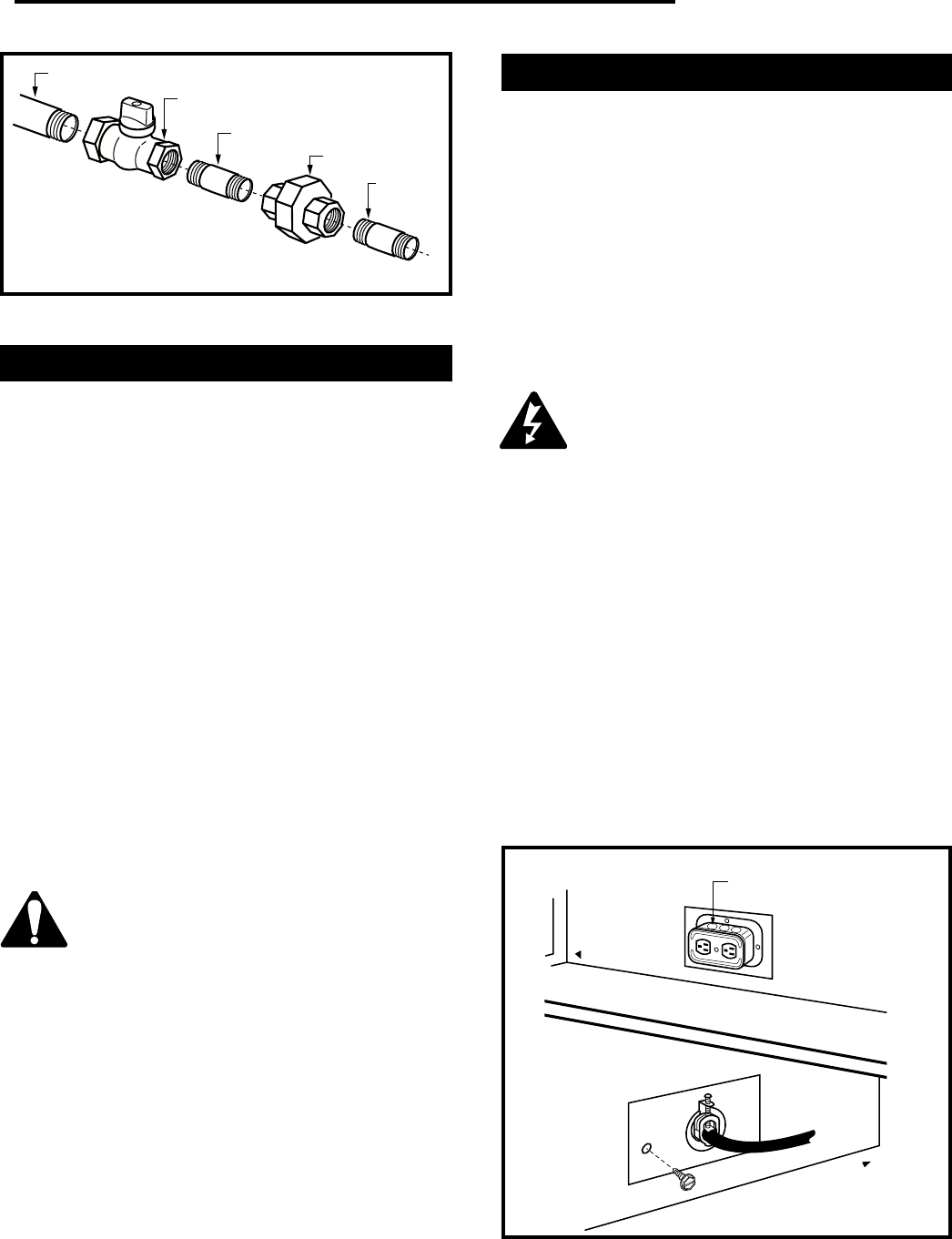
Once the firebox is secured, complete wiring the fan kit.
Remove knockout in the center of the back of the EB1
and install listed cable clamps. Feed electrical wire
through cable clamp leaving approximately 6" of wire
exposed through the EB1. Secure the cable clamp to
the wire.
Attach white wire from power source to one wire of
receptacle and secure with a nut. Attach black wire from
power source to the other wire of the receptacle and
secure with a nut. Be sure nuts are tightened securely.
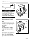
Secure the EB1 assembly to the inside of the electrical
box cover plate using 2 screws. Attach the cover to the
face of the EB1 while being careful to position the
excess wire completely within the EB1. Attach the
coverplate to the firebox. (Fig. 7)
FP598
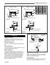
Fig. 6 Typical gas supply line.
1/2" Gas Supply
1/2" x 3/8" Shut-Off Valve
3/8" Nipple
3/8" Union
3/8"
Nipple
Fig. 7 Junction box (EB-1) hook-up.
FP580
Inside
Front of Unit
Electrical Box
Front of Unit
Outside
(Left Side)