


6
UVSRC Series Fireboxes
20002068
Installation
Planning
In planning the installation for the firebox it is necessary
to determine where the unit is to be installed and
whether optional accessories are desired. Gas supply
piping should also be planned.
These models MAY NOT be installed in OEM mobile
homes.
These models MAY BE installed in a bedroom
provided the logset installed in the unit is certified
and rated at 10,000 BTU's or less.
These models MAY NOT be installed in a bathroom.
Glass doors are NOT to be used on these fireboxes.
The firebox can be mounted on any of the following
surfaces:
• A flat hard combustible surface.
• A raised platform of combustible or non-combus-
tible material.
• A concrete block or other solid object placed
beneath each of the four corners of the appli-
ance.
If the firebox is installed directly on carpeting, tile or
other combustible material other than wood flooring, it
should be installed on a metal or wood panel extending
the full width and depth of the unit.
At this point, you should have decided what compo-
nents to include in your installation, and where the
firebox is to be located. If this has not been done, stop
and consult your dealer for assistance with this plan-
ning.
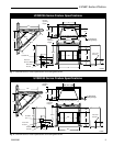
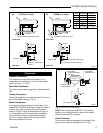
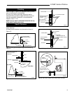
Framing
Firebox framing can be built before or after the firebox
is set in place. Framing should be positioned to accom-
modate wall covering and firebox facing material. The
firebox framing should be constructed of 2 x 4 or
heavier lumber. The framing headers may rest on the
top of the firebox standoffs. Refer to Figures 1 & 2 for
firebox framing dimensions.
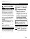
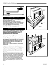
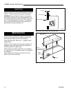
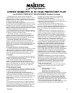
Anchor Firebox Into Position
To prevent shifting of the firebox and to maintain
sealing (described later), anchor the firebox.
Use the four fastening tabs provided with the firebox
and nails or other suitable fasteners to secure the
firebox to vertical framing members. (Fig. 5)
Installing Outside Air Kit
An outside air kit may be installed in all UVSRC Series
fireboxes. If desired, or if local codes mandate the use
of an air kit, then an AKU1 is required to complete the
installation (from air kit to the outdoors). If the outside
air kit is to be used, the AKU1 MUST be installed
BEFORE the fireplace is enclosed. Refer to the AKU1
instructions for field installation.
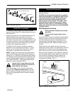
Connect the Gas Line
Gas access holes are provided on both sides of the
firebox.
Check gas valve type. Use only the gas type indicated
on the gas log rating plate. If the gas listed on the plate
is not your type of gas supply, DO NOT INSTALL.
Contact your Dealer for proper model.
Always use an external regulator for all LP fireboxes to
reduce the supply tank pressure to a maximum of 14"
w.c. This is in addition to the regulator fitted to the vent-
free heater.
WARNING: CONNECTION DIRECTLY TO
AN UNREGULATED LP TANK CAN
CAUSE AN EXPLOSION.
For final connection of the gas log heater to the gas line
see Section 5 and Figure 6.
FP606a
Fig. 5 Fasten firebox in position using the nailing flanges.
Top
Standoff
Nail Side-
Nailing
Flanges