


• Maximum Smart Recovery time is one hour.
• The Smart Recovery temperature set point must
be achievable. If a desired smart recovery is
repeatedly ignored by your thermostat. That is an
indicator that you should modify your program so
that the recovery can be achieved within the 1
hour limit.
• A Smart Recovery may not be initiated for 48
hours after the units programs have been
changed. This allows the unit to gather the data
necessary to predict a Smart Recovery time.
7.3. TEMPERATURE DISPLAY FORMAT
˚F/˚C SWITCH #3
The position of this switch controls whether the
temperature is displayed in degrees ˚F or ˚C.
7.4. 5 MIN / 2 MIN MINIMUM RUN TIME
SWITCH #4
The position of this switch controls minimum
length of time the thermostat must remain with
Heat or Cool either ON or OFF before it will
automatically switch to the alternate ON or OFF
state. This feature prevents short cycling and
provides compressor protection for cooling units.
Choices are 2 or 5 minutes.
7.5. REPOSITIONING SWITCHES
Use this table to determine the positions which
correspond to the operation you prefer.
This table is printed on the circuit board.
To
change a switch position move switch down or up.
After settings have been changed with batteries
installed, press the Hardware Reset (H.W. Reset)
button on the rear of the unit's circuit board for
changes to take effect. See jumper and switch
positions figure on Page 12.
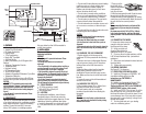
7.6. GAS/ELECTRIC JUMPER
In HEAT mode, the position of this jumper controls
when the thermostat requests the system fan to
run. In Gas mode the fan is normally controlled by
the heating system itself. In Electric mode, the fan
is controlled by the thermostat. See jumper and
switch positions figure on Page 12.
8. BATTERIES AND MAINTENANCE
The PSP711TS requires batteries to operate your
heating/cooling system. Replace the batteries
when the battery
REPLACE
indicator appears in
the display or
at least once a year
.
1. To access your units batteries remove the unit
from the wall by pressing up on the thumb latch at
the bottom of thermostat and swinging the body
up and away to remove it from the wall.
2. Remove the used batteries. See battery location
and polarity in figure on Page 12.
3.
Install two new Energizer
®
or DURACELL
®
"AA" size alkaline batteries in the battery
compartment. Observe the polarity marking
shown in the compartment.
4. Hang the top of the unit by the tabs at the top
corners of the base, then snap the bottom of the
unit into place. Do not use unnecessary force. If
the body does not snap into place easily, remove
the body, re-hang it from the tabs and try again.
9. TECHNICAL ASSISTANCE
If you have any problems installing or using this
thermostat, please reread the instructions carefully
or visit our online technical support at
www.luxproproducts.com
. If you require
assistance, please call our Technical Assistance
number between 8:00 a.m. and 4:30 p.m. Eastern
Standard Time, Monday through Friday. The
number is (856) 234-8803.
10. WARRANTY
Limited Warranty: If this unit fails because of
defects in materials or workmanship within one
year of date of original purchase, LUX will, at its
option, repair or replace it. This warranty does not
cover damage by accident, misuse, or failure to
follow installation instructions. Implied warranties
are limited in duration to one year from date of
original purchase. Some states do not allow
limitations on how long an implied warranty lasts,
so the above limitation may not apply to you.
Please return malfunctioning or defective units to
the participating retailer from which purchase was
made, along with proof of purchase. Please refer
to
"Technical ASSISTANCE"
before returning
thermostat. Purchaser assumes all risks and
liability for incidental and consequential damage
resulting from installation and use of this unit.
Some states do not allow the exclusion of
incidental or consequential damages, so the above
exclusion may not apply to you. This warranty
gives you specific legal rights and you may also
have other rights which vary from state to state.
Applicable in the U.S.A. only.
8
12hr
24hr
1U4
SR=OFF
SR=ON
2
F
C
3
5min
2min
4
9
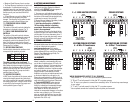
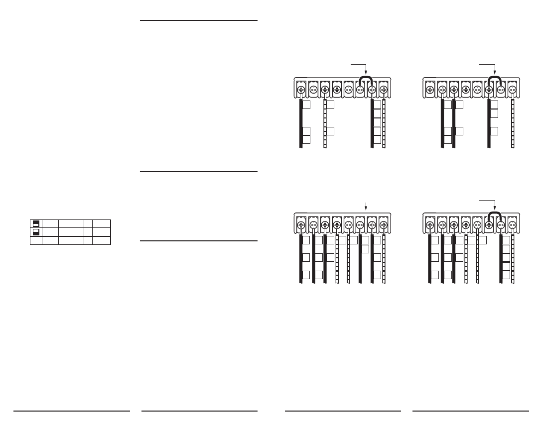
HEATING/COOLING SYSTEMS
5 + 6 Wire 2 Transformers
COMMON FOR SYSTEM POWER
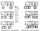
2 + 3 WIRE HEATING SYSTEMS
COMMON FOR SYSTEM POWER
HEATING/COOLING SYSTEMS
4 + 5 Wire 1 Transformers
COMMON FOR SYSTEM POWER
COOLING SYSTEMS
COMMON FOR SYSTEM POWER
CRHRCOBGYW
W
H
4
Y
C*
6
G
F
RC
R
RH
V
5
JUMPER
REMOVED
NOTE: "G" WIRE IS
OMITTED FOR
2 WIRE SYSTEMS
B* O
CRHRCOBGYW
RH
RC
R
V
5
G
F
W
H
4
JUMPER
PROVIDED
CRHRCOBGYW
W
H
4
Y
C*
6
G
F
RH
RC
R
V
5
B* O
CRHRCOBGYW
RH
R
V
G
F
Y
C*
6
JUMPER
PROVIDED
JUMPER
PROVIDED
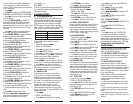
WIRING DIAGRAM NOTES (APPLIES TO ALL DRAWINGS)
* Verify whether “C”, “X” or “B” wires are connected to system common.
* If “B” and “O” are both present, it is likely that “B” is a system common.
* If a “B” wire in your system is a common, then connecting it to the “B” terminal may cause damage
to your system.
* If “Y” and “C” are both present, it is likely that “C” is a system common.
* Use an optional common wire to allow the system to power your thermostat.
3.6. WIRING DIAGRAMS