


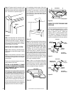
NOTE: DIAGRAMS & ILLUSTRATIONS NOT TO SCALE.
6
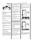
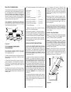
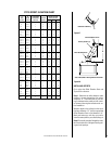
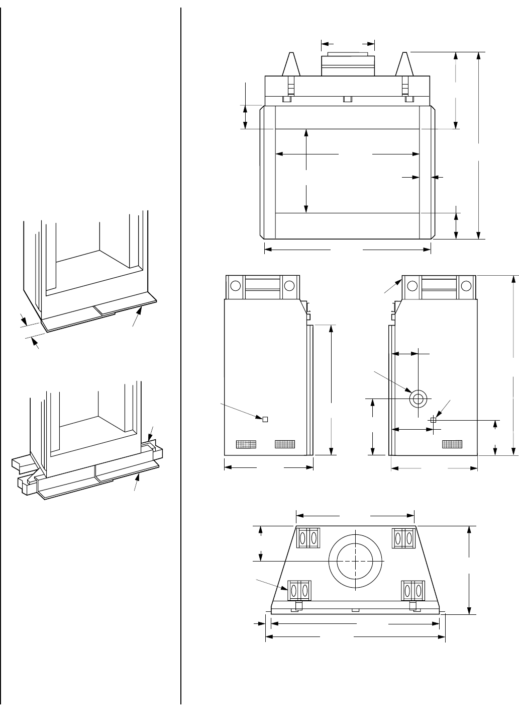
FIREPLACE SPECIFICATIONS
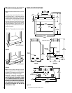
Figure 10
Figure 8
Figure 9
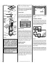
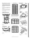
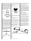
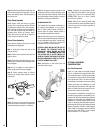
Blocking
Metal Safety Strips
Note: Safety strips are not required when fire-
place rests on a noncombustible surface.
Note: Install the hearth extension only as illus-
trated.
The safety strips should extend from front of
the fireplace at least 1 ¹⁄₂" and should extend to
be at least flush with the sides. In the event a
wooden support is used to elevate the fireplace
above the floor, a “Z” type safety strip should be
fabricated and used to protect the front surface
of the wood support as well as the floor beneath
the hearth extension (
Figures 8 and 9
). The
safety strips should be tacked down to prevent
possible movement.
Note: The “Z” type safety strip is not supplied.
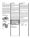
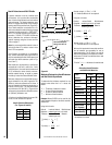
Step 3. Refer to fireplace drawings and specifi-
cations on pages 6 and 7 for framing dimensions
and details. Frame appliance enclosure as illus-
trated in
Figures 11 through 14
on page 7.
IMPORTANT: UNDER NO CIRCUMSTANCES
CAN THE FIREPLACE TOP SPACERS (
FIGURE
10
) BE REMOVED OR MODIFIED, NOR MAY
YOU NOTCH THE HEADER TO FIT AROUND OR
BE INSTALLED LOWER THAN THE SPACERS.
THE HEADER MAY BE IN DIRECT CONTACT
WITH THE TOP SPACERS BUT MAY NOT BE
SUPPORTED BY THEM.
49 ¹⁄₂"
(1257 mm)
31 ¹⁄₂"
(800 mm)
9 ⁵⁄₈"
(244 mm)
Top View
Right Side
Gas Line
Access
Combustion
Air Inlet
7 ¹⁄₂"
(190 mm)
52 ³⁄₄"
(1340 mm)
26 ¹⁄₈"
(664 mm)
26 ⁵⁄₈"
(676 mm)
Left Side
49 ¹⁄₂"
(1257 mm)
Front
52 ³⁄₄"
(1340 mm)
7 ³⁄₄"
(197 mm)
41 ¹⁄₄"
(1048 mm)
4 ¹⁄₈"
105 mm)
15"
(381 mm)
25"
(635 mm)
20"
(508 mm)
7 ¹⁄₈"
(181 mm)
Fireplace Top Spacer
Fireplace
Top Spacer
Gas Line
Access
22 ⁵⁄₈"
(575 mm)
9 ³⁄₄"
(248 mm)
51 ¹⁄₂"
(1308 mm)
1"
(25 mm)
39 ⁷⁄₈"
(1013 mm)
26 ⁵⁄₈"
(676 mm)
16 ¹⁄₄"
(413 mm)
Metal Safety Strips
1 ¹⁄₂"