


NOTE: DIAGRAMS & ILLUSTRATIONS NOT TO SCALE.
11
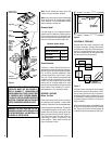
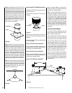
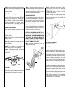
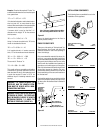
A ¹⁄₈" diameter hole must be drilled in the
chimney joint using a ¹⁄₈" diameter drill. Hole
should be drilled in center of joint overlap
(
Figure 37
). Be sure to drill only through the
outer chimney casting. Do not puncture the
inner flue.
Maximum offset of chimney system is 30°.
Two offsets must not be assembled to form a
60° offset. However, two sets of offset and
return elbows may be used on a single flue
system, provided the total height of the sys-
tem exceeds 25'.
Return elbow support straps must be securely
attached under tension (in shear) to structural
framing members above. Do not substitute a
FTF10-30 offset elbow in place of a FTF10-E30
return elbow.
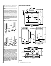
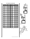
OFFSET CALCULATIONS
Step 1. Use Offset Chart to determine amount
of horizontal offset (A) and height (B) for
various chimney section assemblies.
Step 2. Use “Height of Chimney Only” column
in The Vertical Elevation Chart to determine
combinations of chimney used above return
elbow to achieve desired heights. Reference
Components Effective Height Chart in vertical
elevation chart section.
Step 3. Use Elevation Chart as job estimator
only. Add necessary firestop spacers and sta-
bilizers as required. Firestop spacers must be
used as shown in
Figures 21 and 22
and
stabilizers as shown in
Figure 26
.
3. The effective heights of the components are:
The Fireplace = 52"
FTF10-12 = 10 ¹⁄₄"
FTF10-18 = 16 ¹⁄₄"
FTF10-36 = 34 ¹⁄₄"
FTF10-CTD Termination = 4"
FTF10-CT1 Termination = 12" to 18"
FTF10-CT2 Termination = 15" to 23"
FTF10-CTDT Termination = 12" to 18"
FTF10-S4 Stabilizer * = 3"*
* Required for every 30' of vertical chimney
and/or 10' of offset chimney.
4. Determine amount of chimney height re-
quired by subtracting total combined height of
all pre-selected components (fireplace and
chimney components from total desired height.)
Reference Vertical Elevation Chart and deter-
mine the number of chimney sections (quantity
and length) required.
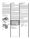
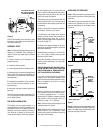
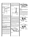
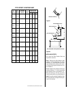
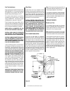
SPECIAL OFFSET INSTRUCTIONS
To clear any overhead obstructions, you may
offset your chimney system using Security
Chimneys 30° offset and return elbows. Use
two elbows - an offset elbow to initiate the
offset and a return elbow to terminate it. A 30°
offset elbow, angling in any direction, may be
the first component used off the top of the
fireplace flue collar.
The offset and return elbows may be attached
together, or a section or sections of chimney
may be used between, but do not exceed 20' in
total length between elbows. If sections of pipe
exceed 10' between elbows, a chimney stabi-
lizer must be used at the midpoint (
Figure 34
).
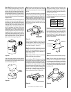
The stabilizer support straps must be attached
under tension (in shear) to structural framing
members above. When two sets of elbows are
used, the maximum combined length of chim-
ney used between elbows cannot exceed 20'
(
Figure 35
). Example: If C
1
= 10' then C
2
cannot
exceed 10'.
If an offset exceeds 6' in length, each chimney
joint beyond the first 6' of offset to the return
elbow, must be secured by a No. 8 x ¹⁄₂" sheet
metal screw located at the underside of the
joint (
Figure 36
).
CTD
18"
18"
24"
24"
CTDT
CTDT
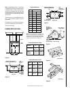
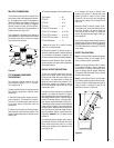
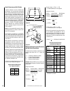
MULTIPLE TERMINATIONS
If more than one termination is located in the
same chase or within the same general proxim-
ity, we suggest they should be separated in
distance at least 24" horizontally from flue cen-
ter to flue center and stacked or staggered
vertically at least 18" apart, from the termina-
tion of one smoke exit to the termination of
another smoke exit (
Figure 33
).
This suggestion is provided in the interest of
better operation. If the terminations are located
too close to each other, smoke may migrate
from one flue into the other.
Figure 33
FTF10 CHIMNEY COMPONENT
CALCULATIONS
The minimum installed height of the com-
pleted fireplace system is 15' 0". The maxi-
mum height is 60' 0".
To determine the number of chimney sections
and chimney components required, follow
these steps:
1. Determine total vertical height of the fire-
place installation. This dimension is the dis-
tance from the surface the fireplace sets on
to the point where smoke exits from the
termination.
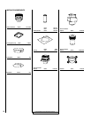
2. Determine the number of chimney compo-
nents required, except chimney sections. This
would include firestop spacers, stabilizers, roof
flashing, etc.
Figure 34
Stabilizer
A
1
20'
Max.
B
1
10' Max.
Offset
Elbow
Return
Elbow