


NOTE: DIAGRAMS & ILLUSTRATIONS NOT TO SCALE.
5
DO NOT permanently place furniture or other
items such as decorative pillows within 60" of
the fireplace front face.
ASSEMBLY STEPS
Note: The following steps represent the normal
sequence of installation. Each installation is
unique, however, and might require a different
sequence.
1. Position firebox prior to framing or into
prepared framing.
2. Install the chimney system.
3. Install optional outside combustion air kit.
4. Plumb gas line if a decorative gas appliance
will be used. (Gas connections should only be
performed by an experienced, licensed/certi-
fied tradesman.)
5. Complete the installation, finish wall mate-
rial, surround and hearth extension to your
individual taste.
6. Assemble and attach optional glass door
assembly.
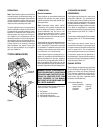
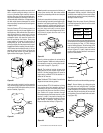
Study the three dimensional illustration (
Fig-
ure 1
) to get a general idea of each element of
your fireplace system.
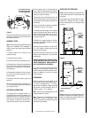
PRE-INSTALLATION NOTES
The fireplace may be installed directly on a
combustible floor or raised on a platform of an
appropriate height. Do not place fireplace on
carpeting, vinyl or other soft floor coverings. It
may, however, be placed on flat wood, ply-
wood, particle board or other hard surfaces.
Figure 5
Figure 7
Figure 6
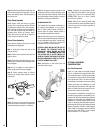
INSTALLING THE FIREPLACE
Step 1. Slide the fireplace into prepared fram-
ing or position fireplace in its final position and
frame later.
The fireplace may not be recessed into a com-
bustible floor. Maintain the floor to hearth
clearance established by the fireplace lower
front face.
Be sure fireplace rests on a solid continuous
floor or platform with appropriate framing for
support and so that no cold air can enter the
room from under the fireplace.
The fireplace may be positioned and then the
framing built around it, or the framing may be
constructed and the fireplace positioned into
the opening.
Usually, no special floor support is needed for
the fireplace, however, to be certain:
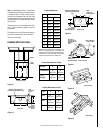
1. Estimate the total weight of the fireplace
system including chimney and surround ma-
terials such as brick, stone, etc., to be in-
stalled. Shipping weights for the fireplace may
be found on page 18.
2. Measure the square footage of the floor
space to be occupied by the system, surrounds
and hearth extensions.
3. Note the floor construction, i.e. 2 x 6’s, 2 x 8’s
or 2 x 10’s, single or double joists, type and
thickness of floor boards.
4. Use this information and consult your local
building code to determine if you need addi-
tional support.
CAUTION: DO NOT BLOCK THE HEAT-CIRCU-
LATING AIR INLET AND OUTLET PORTS ON
CIRCULATING MODELS. DOING SO MAY RE-
SULT IN A POTENTIAL FIRE HAZARD.
If you plan to raise the fireplace and hearth
extension, build the platform assembly then
position fireplace and hearth extension on top.
Secure the platform to the floor to prevent
possible shifting.
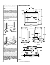
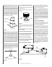
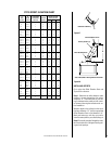
CLEARANCES
Minimum clearance to combustibles for the
LA41 fireplace is as follows; sides and back –
2" (51mm), combustible floor – 0" (0mm),
adjacent wall 20" (508mm), adjacent shielded
wall (
K factor of .54 or less 24" W x 36" H
) 14"
(356mm), ceiling – 37 ¹⁄₂" (953mm).
Note: Clearance at the nailing flange for both
fireplace models is 0" (0mm).
Note: Adjacent wall considerations are for an
adjacent wall on only a single side. Walls
should not be placed at minimum distance at
both sides of the fireplace.
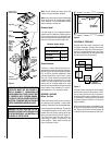
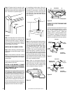
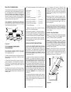
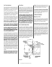
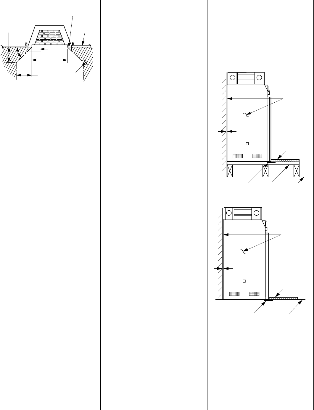
Metal Safety Strip Floor
Hearth
Extension
Platform
2" (51 mm)
Space
Maintain
2" (51 mm)
Air Space
At Back
And Sides
Metal Safety Strip Floor
Hearth
Extension
2" (51 mm)
Space
Maintain
2" (51 mm)
Air Space
At Back
And Sides
Step 2. Insert the provided metal safety strips,
beneath the fireplace as illustrated (
Figures 6, 7
and 8
). The safety strips should overlap ¹⁄₂" for
continual coverage of the floor.
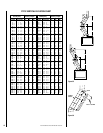
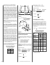
Wall
Covering
Black Portion Of Frame
Not To Be Covered With
Combustible Materials
Safe
Zone
45°
20”
Door
Opening
1”
20”