


Operation – Main Console
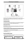
The Main Console is the heart of the security system. It monitors the sensors and
responds according to how it is programmed, whenever a sensor is activated. The
illustration shown for the Main Console may look complex at first, however, most
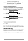
procedures are straightforward and easy. Please review the illustration below, which
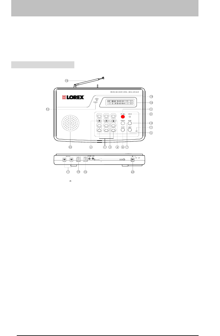
labels all the parts of the Main Console.
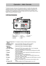
LCD Panel Illustration
#
123
4
56
7
8
9
0
MICROPROCESSOR CONTROL KEYPAD
LEGEND
1 . NUMERIC AND #, BUTTONS
2 . BURGLARY BUTTON
3 . FIRE BUTTON
4 . MEDICAL EMERGENCY BUTTON
5 . SP DIAL BUTTON
6 . CHECK BUTTON
7 . CANCEL BUTTON
8 . ENTER BUTTON
9 . AWAY BUTTON
17 . OUTPUT TERMINAL JACKS
16 . ANTENNA
15 . SPEAKER
14 . LCD PANEL
13 . ARMED LED INDICATOR
12 . POWER LED INDICATOR
11 . MIC
20 . DC POWER JACK
19 . TEL LINE JACK
18 . TELEPHONE JACKS
10 . HOME BUTTON
1. Numeric keys and
# keys
: For telephone setting include the pound and star keys.
2. Burglary Button : Press the SP DIAL & Burglary Buttons together
3. Fire Button : Press the SP DIAL & Fire Buttons together
4. Medical
Emergency
: Press the SP DIAL & Fire Buttons together
5. SP DIAL button : Press the SP DIAL button together with 4, 5 or 6 to activate
one of the 3-emergency dialing numbers
6. Check : Press the CHECK button to review sensor settings and to check
recorded message.
7. Cancel : Press the CANCEL button to go back to the previous menu or to
delete the Message
8. Enter : Press ENTER to confirm program entry.
9. Away : Key-in the “ Master ” code, then press the AWAY button to arm
the system in the away mode
10. Home : Key-in the “ Master ” code then press the HOME button to arm the
system in the home mode
11. Mic
s
ed to record messages, and for two way communication voice
input.
12. Power LED : Indicates whether the AC Adaptor power is on or off.
6