


63
11 Operating information (continued)
Monitor external limits
Connections are provided on the connection board for
external limits such as fl ow switch, low water cutoff,
gas pressure switches, and a louver proving switch. The
SMART SYSTEM will shut off the burner and inhibit
relighting whenever any of these external limits open.
Run-time and alarm outputs
The boiler provides dry contacts for indicating when the
boiler is running, and when it is unable to operate.
Run-time and cycle counting
The control uses two timers to monitor the total hours of
burner operation. One timer monitors the time the boiler
is in the Space Heating Mode. The other timer monitors
the time the boiler is fi ring in the DHW Mode.
The control uses two (2) ignition counters to monitor
the amount of boiler cycles. The fi rst counter counts all
ignitions of the control. The second counter counts only
ignition attempts that have failed.
Service reminder
The control can be programmed for service reminder
notifi cation. This notifi cation will become active when
either a set time frame has expired, or a set amount of
running hours or cycles has expired (all adjustable by the
installer). The display will show a Maintenance Required
screen. The service reminder notifi cation can be reset or
disabled by the installer.
The time dependent feature has been disabled by the
manufacturer. To enable this feature change parameter K1
to the desired time range, reference the Knight XL Service
Manual for details regarding parameters.
Error logging
The control will hold in memory the last 10 lockouts as
well as the last 10 blockings. The date and time of the
occurrence will be recorded as well. Only the 10 most
current occurrences of each will be held in memory.
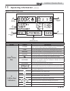
Boiler temperature regulation
Operating temperature (target)
The SMART SYSTEM control module senses water
temperature and regulates boiler fi ring and fi ring rate to
achieve a target temperature. The target temperature can
be set between 70°F (21°C) and 190°F (88°C).
• Target temperature is fi xed when the outdoor
sensor is not installed.
• Target temperature is calculated as described
on this page under “Outdoor Reset Operation”
and “Target Temperature Boost” when the
outdoor sensor is connected.
High limit operations
The Knight XL is equipped with adjustable automatic reset and
manual reset high limits. The automatic reset high limit has a
maximum set point of 200°F and the manual reset high limit
has a maximum set point of 210°F.
When the outlet temperature exceeds 200°F, the automatic
high limit action occurs. The boiler shuts down until the outlet
water temperature cools below 190°F, and a 60 second timer
has expired. If the outlet temperature continues to increase, the
manual reset high limit action will occur at 210°F.
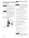
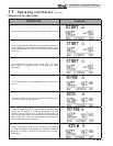
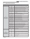
High limit test procedure
1. Turn ON the main power to the boiler by placing the
ON/OFF switch in the ON position.
2. If boiler status reads [SHUTDOWN] place the boiler into
the active position by pressing the RIGHT SELECT [ON]
key.
3. Locate the pinhole (SERVICE button) below the RESET
button on the display board. Insert a thin wire (such as a
paper clip) into the hole and press the button once, hold
for fi ve (5) seconds to place the boiler into Service Mode.
In Service Mode the boiler will fi re at ignition speed and
will then modulate up to full fi re.
4. From the Status Screen, press the NAVIGATION dial to
access the Set Points Screen.
5. Press the LEFT SELECT [LIMITS] key.
6. Select the manual reset high limit (MRHL) by pressing the
NAVIGATION dial.
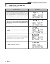
7. Decrease the set point of the MRHL below the outlet
temperature by turning the NAVIGATION dial
counterclockwise.
8. Press the RIGHT SELECT [SAVE] key.
9. Press the RIGHT SELECT [HOME] key.
10. The new parameters will upload to the control and the
MRHL will function causing boiler shutdown and
[LOCKOUT] to be displayed.
11. Press the RESET button to clear the lockout.
12. Repeat Steps 4, 5 and 6.
13. Set the MRHL to the appropriate set point by turning the
NAVIGATION dial clockwise.
14. Repeat Steps 8 and 9.
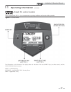
Please note that the brackets ([]) denote
screen status.
NOTICE
Installation & Operation Manual