


21
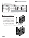
Model Kit Number
Equivalent
Vent Length
400 CVK3007 5 Feet (1.5 m)
501 CVK3007 30 Feet (9 m)
601 CVK3007 30 Feet (9 m)
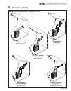
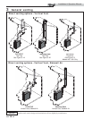
3 General venting (continued)
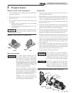
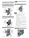
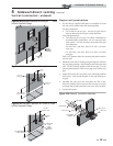
Vent, air piping and termination:
The Knight XL vent and air piping can be installed through the
roof or through a sidewall. Follow the procedures in this manual
for the method chosen. Refer to the information in this manual
to determine acceptable vent and air piping length.
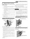
Removing from existing vent
Follow the instructions in Section 1, page 12 of this manual
when removing a boiler from an existing vent system.
Vent and air piping
Vent and air system:
Installation must comply with local
requirements and with the National Fuel Gas
Code, ANSI Z223.1 for U.S. installations or
CSA B149.1 for Canadian installations.
You must also install air piping from outside to the boiler air
intake adapter. The resultant installation is direct vent (sealed
combustion).
You may use any of the vent/air piping methods covered in this
manual. Do not attempt to install the Knight XL using any
other means.
DO NOT mix components from different
systems. The vent system could fail,
causing leakage of fl ue products into the
living space. Use only approved stainless
steel, PVC or CPVC pipe and fi ttings. For
PVC/CPVC use with primer and cement
specifi cally designed for the material used.
NOTICE
ƽ WARNING
Table 3E Concentric Vent Kit Equivalent Vent Lengths
The appliance output rating will reduce
by up to 1.5% for each 25 feet (68 m) of
vent length.
NOTICE
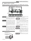
Minimum / Maximum allowable
combustion air and vent piping lengths
are as follows:
Combustion Air = 12 equivalent feet (3.7 m) minimum /
100 equivalent feet (30.5 m) maximum
Vent = 12 equivalent feet (3.7 m) minimum / 100 equivalent
feet (30.5 m) maximum
When determining equivalent combustion air and vent
length, add 5 feet (1.5m) for each 90° elbow and 3 feet (.9 m)
for each 45° elbow.
EXAMPLE: 20 feet (6 m) of PVC pipe + (3) 90° elbows +
(3) 45° elbows + (1) concentric vent kit (CVK3007) = 49
equivalent feet (15 m) of piping.
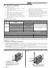
Model Air Intake Vent
400 - 601 4 inches (102 mm) 4 inches (102 mm)
701 - 801 4 inches (102 mm) 6 inches (152 mm)
The Knight XL uses model specifi c combustion air intake and
vent piping sizes as detailed in Table 3D below.
Table 3D Air Intake/Vent Piping Sizes
Increasing or decreasing combustion air
or vent piping is not authorized.
NOTICE
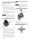
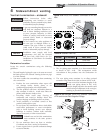
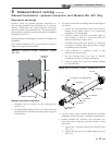
Optional room air
Commercial applications utilizing the Knight XL boiler may
be installed with a single pipe carrying the fl ue products to the
outside while using combustion air from the equipment room.
In order to use the room air venting option the following
conditions and considerations must be followed.
• The unit MUST be installed with the appropriate
room air kit (Table 3F).
• The equipment room MUST be provided with
properly sized openings to assure adequate
combustion air. Please refer to instructions provided
with the room air kit.
• There will be a noticeable increase in the noise level
during normal operation from the inlet air opening.
• Using the room air kit makes the unit vulnerable to
combustion air contamination from within the
building. Please review Section 1, Prevent
Combustion Air Contamination, to ensure proper
installation.
• Vent system and terminations must comply with the
standard venting instructions set forth in this manual.
NOTICE
Optional room air is intended for
commercial applications. Combustion air
piping to the outside is recommended for
residential applications.
Installation & Operation Manual