


2 Prepare boiler
13
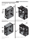
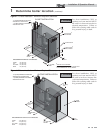
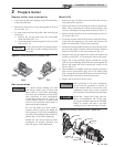
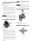
Remove boiler from wood pallet
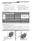
1. After removing the outer shipping carton from the boiler,
remove the parts box.
2. Remove the front door to access the lag bolts in front of
the unit (FIG. 2-1).
3. To remove the boiler from the pallet (after removing the
front door):
a. Remove the two lag bolts from the wood pallet
inside the boiler (FIG. 2-1).
b. Detach the boiler from the lag bolts in the rear of the
unit, see FIG. 2-1.
Do not drop the boiler or bump the jacket
on the fl oor or pallet. Damage to the boiler
can result.
For a boiler already installed, you must
turn off gas supply, turn off power and
allow boiler to cool before proceeding.
You must also completely test the boiler
after conversion to verify performance
as described under Start-up, Section 10
of this manual. Failure to comply could
result in severe personal injury, death, or
substantial property damage.
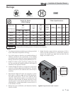
For the 400 Model you must install a
propane orifi ce to operate the Knight XL
on propane gas. Verify when installing that
the orifi ce size marking matches boiler size
(Model 400 - 8.0 LP orifi ce stamping).
Models 501 - 801 do not require an orifi ce
installation for propane operation, but
they will require a valve adjustment.
. 2
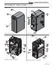
Figure 2-1 Boiler Mounted on Shipping Pallet
Gas conversions
NOTICE
ƽ WARNING
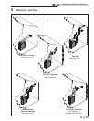
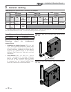
BLOWER
O-RING
VENTURI
SCREWS
QTY. 3
GAS VALVE
BRASS ORIFICE
O-RING
SCREWS
QTY. 4
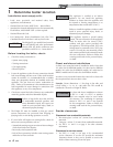
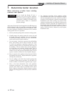
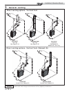
Figure 2-2 Installing Propane Orifi ce - Model 400
Model 400
1. Remove the top and front access covers from the unit (no
tools required for removal).
2. Remove the three screws securing the venturi to the blower.
Note: When separating the venturi from the blower, take
care not to damage the O-ring inside the blower (FIG. 2-2).
3. Remove the four star-drive screws securing the gas valve to
the venturi (FIG. 2-2).
4. Locate the propane orifi ce disk from the conversion kit bag.
Verify that the stamping on the orifi ce disk matches the
boiler size (Model 400 - 8.0 LP orifi ce stamping).
5. Remove the existing orifi ce from the O-ring in the side of the
gas valve and replace it with the orifi ce from the kit. Position
and secure the orifi ce in the valve as shown in FIG. 2-2.
6. Reposition the gas valve against the venturi and replace the
star-drive screws (FIG. 2-2) securing the valve to the venturi.
7. Inspect the O-ring inside the blower. Handle the O-ring
with care, do not damage. Reposition the venturi against the
blower and replace the screws securing the venturi to the
blower (FIG. 2-2).
8. After installation is complete, attach the propane conversion
label (in the conversion kit bag) next to the boiler rating
plate. Attach the LP caution label (in the conversion kit bag)
to the left side of the unit in the lower left corner.
9. Replace the top and front access covers.
ƽ DANGER
Model 400: Inspect the O-ring when the
blower is disassembled. The O-ring must
be in good condition and must be installed.
Failure to comply will cause a gas leak,
resulting in severe personal injury or death.
ƽ WARNING
After converting to LP, check combustion
per the Start-up procedure in Section 10
of this manual. Failure to check and verify
combustion could result in severe personal
injury, death, or substantial property damage.
Installation & Operation Manual