


56
10 Start-up
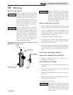
Check for gas leaks
Before starting the boiler, and during
initial operation, smell near the fl oor and
around the boiler for gas odorant or any
unusual odor. Remove the top access
panel and smell the interior of the boiler
enclosure. Do not proceed with startup
if there is any indication of a gas leak.
Use an approved leak detection solution.
Repair any leaks at once.
DO NOT adjust or attempt to measure
gas valve outlet pressure. The gas valve is
factory set for the correct outlet pressure.
This setting is suitable for natural gas and
propane, requiring no fi eld adjustment.
Attempting to alter or measure the gas
valve outlet pressure could result in
damage to the valve, causing potential
severe personal injury, death, or
substantial property damage.
Propane boilers only – Your propane
supplier mixes an odorant with the propane
to make its presence detectable. In some
instances, the odorant can fade, and the
gas may no longer have an odor. Before
startup (and periodically thereafter), have
the propane supplier verify the correct
odorant level in the gas.
Check thermostat circuit(s)
1. Disconnect the two external wires connected to each of
the room thermostat terminals on the connection board.
2. Connect a voltmeter across these two incoming wires.
Close each thermostat, zone valve, and relay in the
external circuit one at a time and check the voltmeter
reading across the incoming wires.
3. There should NEVER be a voltage reading.
4. If a voltage does occur under any condition, check and
correct the external wiring. (This is a common problem
when using 3-wire zone valves.)
5. Once the external thermostat circuit wiring is checked and
corrected if necessary, reconnect the external thermostat
circuit wires to the connection board. Allow the boiler to
cycle.
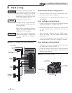
Inspect/fi ll condensate system
Inspect/check condensate lines and fi ttings
1. Inspect the condensate drain line, condensate PVC
fi ttings and condensate trap.
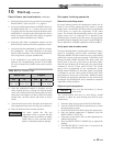
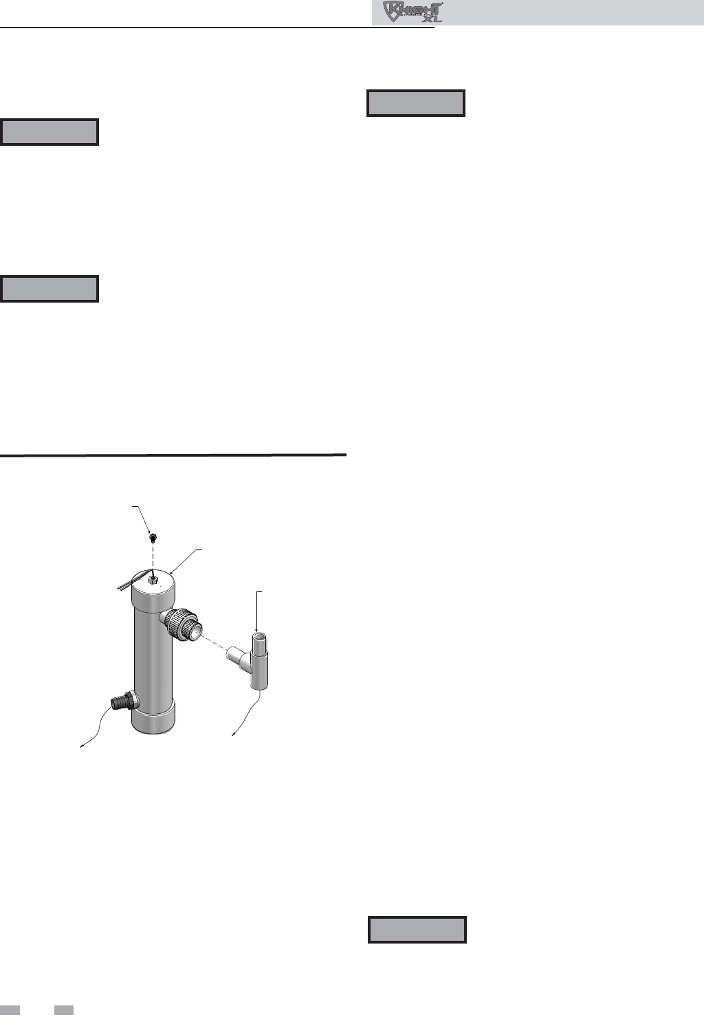
Fill condensate trap with water
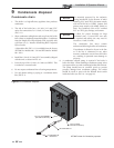
1. Remove the PVC cap retaining screw from the PVC cap
(FIG. 10-1).
2. Remove the 2 inch PVC cap with the switch located at the
top of the trap (FIG. 10-1).
3. Fill with fresh water until the water begins to pour out of
the drain.
4. Replace the cap. Press the cap onto the trap until the cap
makes contact with the drain.
5. Replace the retaining screw.
The condensate trap (FIG. 10-1) must be
fi lled with water during all times of boiler
operation to avoid fl ue gas emission from
the condensate drain line. Failure to fi ll
the trap could result in severe personal
injury or death.
PVC TEE ASSEMBLY
(FACTORY SUPPLIED)
TO FLOOR
DRAIN
2” PVC CAP WITH
BLOCKED DRAIN SWITCH
RETAINING
SCREW
CONDENSATE FROM
HEAT EXCHANGER
Figure 10-1 Condensate Trap
ƽ WARNING
ƽ WARNING
ƽ WARNING
ƽ WARNING
Installation & Operation Manual