


64
Installation & Operation Manual
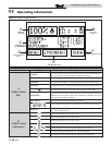
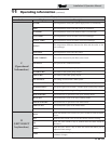
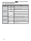
11 Operating information
DHW, Night Setback, and Ramp Delay operation with
cascade
For normal mode DHW operation any boiler(s) in the Cascade
can be selected to provide heat for a DHW call. Select a boiler to
be designated as the DHW boiler. Connect the DHW thermostat
or sensor to the terminals on the Low Voltage Connection Board
marked for the corresponding device. When the boiler receives a
DHW call, the Leader control will take that boiler out of the
Cascade sequence. If another boiler is available, the Leader will
start it up to take its place.
The DHW boiler will adjust its set point to the programmed
DHW set point and will adjust its firing rate to maintain this.
Once the DHW call has been satisfied, the Leader control will
place that boiler back into the Cascade sequence.
Switching of the boiler between DHW operation and SH
operation when there is a call for both does not occur in Cascade
Mode.
When DHW is programmed for Zone Mode, connect the DHW
thermostat or tank sensor to the Leader boiler. When a DHW
call is received, the Leader will modulate the entire Cascade to
bring the system supply temperature up to the DHW boiler set
point (if higher).
Night Setback operation of the boilers within the Cascade is
available. Programming of the Night Setback will be done
through the Leader boiler. Refer to the Knight Wall Mount
Service manual for information regarding Night Setback.
Ramp Delay operation of the boilers as described in the Knight
Wall Mount Service Manual is not active when the boilers are
part of a Cascade system.
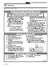
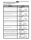
Sequence of the cascade
To equalize the run time of all boilers on the Cascade, the firing
sequence will automatically be changed at set intervals.
For the first 24 hours after initializing the Cascade, the sequence
will be changed every hour. After that the sequence will be
changed once every 24 hours. The switching on/off sequence
will be as follows:
DAY SWITCHING ON SEQUENCE
Day 1 L-M1-M2-M3-M4-M5-M6-M7
Day 1 + 1 hour M1-M2-M3-M4-M5-M6-M7-L
Day 1 + 2 hours M2-M3-M4-M5-M6-M7-L-M1
If a boiler is used to heat an indirect DHW tank, it will
automatically be given the lowest priority.
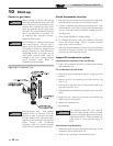
Cascade
When multiple boilers are installed, they can be wired
together in a cascade sequence. A maximum of eight boilers
can be controlled from a single control. In this application
one boiler would be designated as the Leader control and all
others would be designated as Member controls. If installing
the boilers in an existing system, the new boilers should be
programmed as the Leader and/or the higher number
addresses. The Leader control can be programmed to use
Lead/Lag or Efficiency Optimization control methods.
Once the Leader boiler receives a call for heat from a room
thermostat, BMS, or Modbus, the control will determine what
the set point will be. If outdoor air reset is desired, connect the
outdoor air sensor to the terminals on the Low Voltage
Connection Board on the Leader boiler. The set point will be
calculated based on the programmed reset curve parameters.
See the Knight Wall Mount Service Manual to program the
reset curve. If outdoor air reset is not desired, do not connect
the outdoor air sensor. A fixed temperature set point can be
programmed into the control. See page 59 of this manual to
program the set point.
If the water temperature at the system supply sensor is less
than the set point + the turn-off offset - the off-on
differential, then the control will initiate a call for heat on the
Cascade (see the Knight Wall Mount Service Manual for an
explanation of the offset and differential). The Leader will
energize the lead boiler on the Cascade. For a new startup this
will be the Leader boiler.
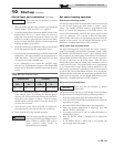
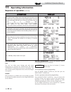
Outdoor reset operation, if used
Target temperature with outdoor reset
This feature improves the system’s efficiency as the outdoor
temperature warms up.
See the Knight Wall Mount Service Manual to change the
settings.
Reset curve
The reset curve looks at outdoor air temperature and adjusts
the set point.