


6 Hydronic piping (continued)
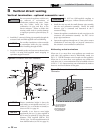
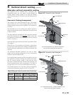
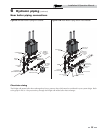
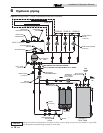
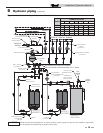
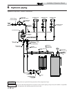
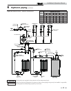
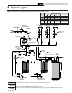
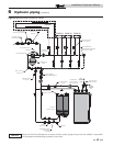
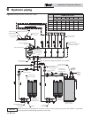
It is required that near boiler piping systems
utilize Primary/Secondary configurations as
shown in FIG.’s 6-3 through 6-10 only. The
use of other near boiler piping configurations
could result in improper building and system
flow rates leading to inadvertent boiler high
limit shutdowns and poor system
performance.
NOTICE
Pump sizing and flow requirements are
based on 20 feet of piping, 4 - 90° elbows,
and 2 - fully ported ball valves.
NOTICE
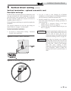
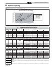
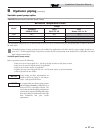
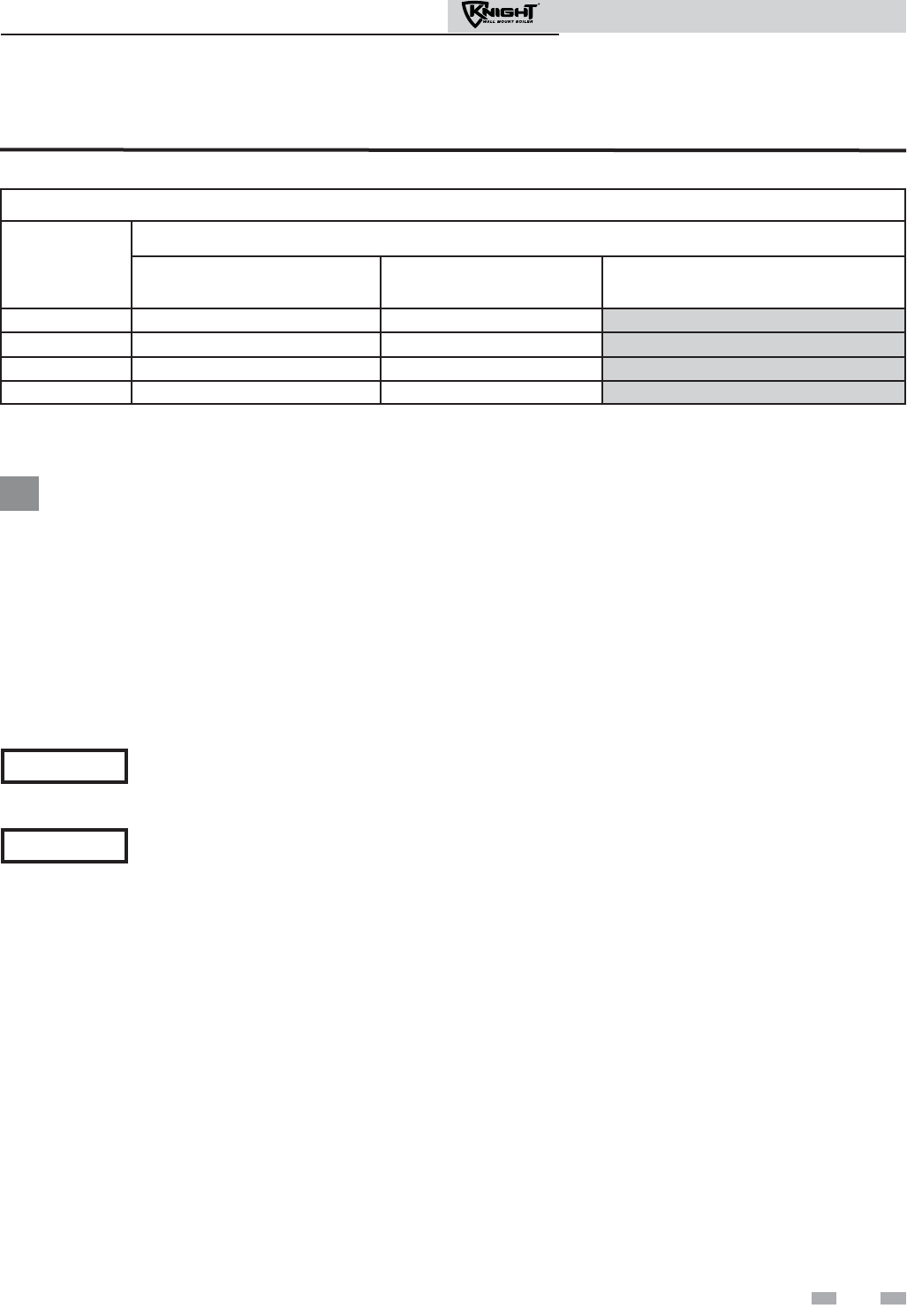
Variable speed pump option
Table 6B Recommended Variable Speed Pumps
*The minimum temperature rise is derived from the chart in FIG. 6-2 with the firing rate and pump speed at 100% as shown in
the table above.
The shaded regions of pump coverage are only available for applications with 230V (60 Hz) supply voltage, all others are
to be 115V. (A field supplied relay is required to connect the 230V pump listed in the shaded area in Table 6B to the boiler
high voltage terminal strip.)
Variable speed pump setup
Before operation, ensure the following:
- Pump is set for an input signal of 0 - 10Vdc by the dip switches on the pump control
- Pump is set for external signal control (if applicable)
- Pump is set for linear output (if applicable)
- If pump does not come equipped with a 0 - 10 Vdc input option, an optional module
will be required from the vendor
37
Installation & Operation Manual
Minimum Temperature Rise*
Model
Pump
Grundfos
UP26-96 FC/VS
TACO
0013 IFC VS
Wilo
Stratos 1.25 3 x 30
51/81 20.3 20.3
21.7
106 22.3 21.0 21.5
151 21.2 19.8
19.1
211 26.8 25.1 23.6