


55
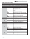
Run-time and alarm outputs
The appliance provides dry contacts for indicating when the
appliance is running, and when it is unable to operate.
Run-time and cycle counting
The control uses two timers to monitor the total hours of burner
operation. One timer monitors the time the appliance is firing
under 50% of rate. The other timer monitors the time the
appliance is firing over 50% rate.
The control uses four (4) ignition counters to monitor the
amount of appliance cycles. The first counter counts all
ignitions of the control. The second counter counts only
ignition attempts that have failed. The third and fourth
counters are the same as the first and second respectively, but
can be reset by the installer.
Service reminder
The control can be programmed for service reminder
notification. This notification will become active when either a
set time frame has expired, or a set amount of running hours or
cycles has expired (all adjustable by the installer). The display
will alternate the standard text on the display screen with Service
Due every 5 seconds. The service reminder notification can be
reset by the installer.
Error logging
The control will hold in memory the last 10 error codes as well
as the last 10 turn-off functions. The date and time of the
occurrence will be recorded as well. Only the 10 most current
occurrences will be held in memory.
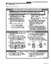
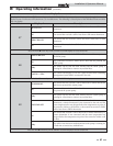
Boiler temperature regulation
Operating temperature (target)
The SMART SYSTEM control module senses water temperature
and regulates appliance firing and firing rate to achieve a target
temperature. The target temperature can be set between 70°F
(21°C) and 220°F (104°C) (boilers) or between 60°F (16°C) and
190°F (88°C) (water heaters).
• Target temperature is fixed when the outdoor
sensor is not installed (boilers).
• Target temperature is calculated as described
under “Outdoor Air Reset Operation” and
“Boost Function” when the outdoor sensor is
connected (boilers).
Outdoor reset operation, if used (boilers
only)
Target temperature with outdoor reset
This feature improves the system’s efficiency as the outdoor
temperature warms up.
See the Power-fin Service Manual to change the settings.
Reset curve
The reset curve looks at outdoor air temperature and adjusts the
set point.
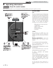
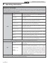
Cascade
When multiple appliances are installed, they can be wired
together in a cascade sequence. A maximum of eight appliances
can be controlled from a single control. In this application one
appliance would be designated as the Leader control and all
others would be designated as Member controls. The set point
or firing rate can be controlled by the 0 - 10V input as well.
Once the Leader appliance receives a call for heat from a BMS,
tank sensor, or external thermostat, the control will determine
what the set point will be. A fixed temperature set point can be
programmed into the control. See page 50 of this manual to
program the set point.
On boilers, if the water temperature at the system sensor is less
than the set point + the turn-off offset - the off-on differential,
then the control will initiate a call for heat on the Cascade (see
the Power-fin Service Manual for an explanation of the offset
and differential). The Leader will energize the lead appliance on
the Cascade. For a new startup this will be the Leader appliance.
On water heaters, if the water temperature at the tank sensor is
less than the tank set point - the off differential, then the control
will initiate a call for heat on the Cascade.
Monitor external limits
Connections are provided on the connection board for external
limits such as a louver proving switch. The SMART SYSTEM
will shut off the burner and inhibit relighting whenever any of
these external limits open.
Low water cutoff protection
1. The SMART SYSTEM control module uses temperature
sensing of both inlet and outlet areas of the heat exchanger.
If the flow rate is too low or the outlet temperature too high,
the control module modulates and shuts the appliance
down. This along with the flow switch, ensures appliance
shutdown in the event of low water or low flow conditions.
2. Some codes and jurisdiction may accept these integral
features of the control in lieu of requiring an additional
limit control or low water cutoff. Consult local jurisdiction
to determine. Contact manufacturer for low water cutoff kit
availability.
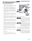
8 Operating information (continued)
Installation & Operation Manual