


44
Installation & Operation Manual
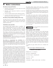
5 Electrical connections
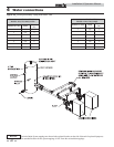
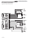
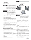
Figure 5-1_Line Voltage Field Wiring Connections
Low voltage connections
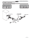
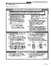
1. Route all low voltage wires through the knockouts in the
rear of the heater, as shown in FIG. 5-2.
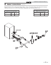
2. Connect low voltage wiring to the low voltage connection
board as shown in FIG. 5-4 on page 46 of this manual and
the heater wiring diagram.
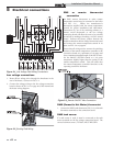
Figure 5-2_Routing Field Wiring
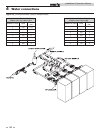
EMS or remote thermostat
connection
An EMS, remote thermostat or other remote
temperature control may be connected to the boiler
(see FIG. 5-3). Follow the manufacturer’s
instructions supplied with the remote temperature
control for proper installation and adjustment.
Connection of a set of dry switching contacts or a
remote on/off thermostat to the low voltage
connection board will allow the unit to be switched
on and off by making or breaking a 24 VAC control
circuit. Remove the factory jumper between the
enable terminals on the low voltage connection board
and connect the remote temperature control in its
place, see FIG. 5-4 on page 46.
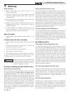
Figure 5-3_Remote ON/OFF Wire Connection
Ensure that all wiring used to connect the switching
contacts of the remote temperature controller to the
connection board are a minimum of 18 gauge and
have a maximum installed length of 300 feet (91.4m).
Set the SMART SYSTEM control to a set point
temperature slightly higher than the setting of the
remote temperature control. This will ensure that
the remote temperature controller functions as the
operating control for the heater.
DHW (Domestic Hot Water) thermostat
1. Connect the DHW tank thermostat (FIG. 5-4) to the tank
thermostat terminals on the connection board.
DHW tank sensor
If a tank sensor is used, it must be connected to the tank
sensor terminals on the low voltage connection board. The
correct Lochinvar sensor (TST2032) MUST BE USED.