


The combination gas valves have an integral vent limiting
device and does not require venting to atmosphere outside the
building. The unit will not operate properly if the reference
hose is removed or a vent to atmosphere is installed.
Optional gas controls may require routing of bleeds and vents
to the atmosphere outside the building when required by local
codes.
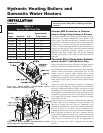
Connecting Gas Piping to Unit
All gas connections must be made with pipe joint compound
resistant to the action of liquefied petroleum (L.P.) and natural
gases. All piping must comply with local codes and
ordinances. Piping installations must comply with approved
standards and practices.
1. Make sure gas line is a separate line direct from the meter
unless the existing gas line is of sufficient capacity. Verify
pipe size with your gas supplier.
2. Use new, properly threaded black iron pipe free from
chips. If you use tubing, make sure the ends are square,
deburred and clean. Make all tubing bends smooth and
without deformation. Avoid flexible gas connections.
Internal diameter of flexible lines may not provide unit
with proper volume of gas.
3. Install a manual main gas shutoff valve at the unit's gas
inlet, outside of the unit.
4. Run pipe or tubing to the unit's gas inlet. If you use tubing,
obtain a tube to pipe coupling to connect the tubing to the
unit's gas inlet.
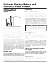
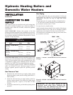
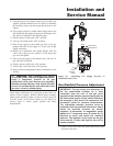
5. Install a sediment trap in the supply line to the unit's gas
inlet (see Figure 17).
6. Apply a moderate amount of good quality pipe compound
(do not use Teflon tape) to pipe only, leaving two end
threads bare.
7. Remove seal over gas inlet to unit.
8. Connect gas pipe to inlet of unit. Use wrench to support
gas manifold on the unit.
9. For L.P. gas, consult your L.P. gas supplier for expert
installation.
10. Ensure that all air is properly bled from the gas line before
starting the ignition sequence. Start up without properly
bleeding air from the gas line may require multiple reset
functions of the ignition control module to achieve proper
ignition.
ƽ WARNING: Do not have any open flame in
proximity to the gas line when bleeding air from
the gas line. Gas may be present.
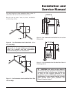
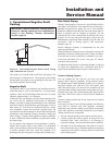
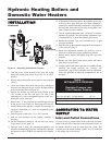
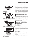
Figure 19 - Gas Train Drawing
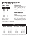
For each elbow or tee, add equivalent straight pipe to total length from table below.
Gas Train and Controls
Note: The gas train and controls assembly provided on this
unit have been tested under the applicable American National
Standard to meet minimum safety and performance criteria
such as safe lighting, combustion and safety shutdown
operation.
Figure 19 shows a typical gas train.
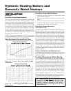
TABLE-F
Installation and
Service Manual
17
COMBINATION VALVE
DOWNSTREAM
TEST VALVE
TO BURNERS
ADDITIONAL VALVES BASED
ON UNIT INPUTS
Btu/hr Distance From Meter (in feet)
Input 0-50 51-100 101-200 201-300 301-500
495,000 1 1/4" 1 1/4" 1 1/2" 2" 2"
645,000 1 1/4" 1 1/2" 2" 2" 2 1/2"
745,000 1 1/2" 2" 2" 2 1/2" 2 1/2"
985,000 2" 2" 2 1/2" 2 1/2" 3"
1,255,000 2" 2 1/2" 2 1/2" 3" 3"
1,435,000 2 1/2" 2 1/2" 3" 3" 3 1/2"
1,795,000 2 1/2" 3" 3" 3 1/2" 3 1/2"
2,065,000 2 1/2" 3" 3" 3 1/2" 4"
TABLE-F
Suggested Gas Pipe Size for Single Unit Installations
Diameter Pipe (inches)
3/4 1 1 1/4 1 1/2 2 3 4 5
Equivalent Length of Straight Pipe (feet)
22345101420
TABLE-G
Fittings to Equivalent Straight Pipe