


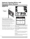

OPERATION
Continued
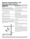
Hot Surface Ignition Control Module
Ignition Module Lockout Functions
The ignition module may lockout in either a hard-lockout
condition, requiring pushing of the reset button to recycle the
control, or a soft-lockout condition which may recycle after an
approximate five-minute waiting period. This soft-lockout
condition is intended to allow self-correcting faults to correct
themselves and permit normal operation. A typical hard-
lockout fault is a flame failure condition. An ignition module
that is in a hard-lockout condition may only be reset by
pushing the reset button next to the ignition control or the
"RESET" button on the diagnostic panel on the left end of the
unit. Upon a flame failure, the reset button is only active after
the control module has completed its post-purge cycle. Turning
main power "OFF" and then "ON" or cycling the thermostat
will not reset a hard-lockout condition. Wait five seconds after
turning on main power before pushing the reset button when
the ignition module is in a hard lockout. The ignition module
will go into a soft lockout if conditions of low air, low voltage
or low hot surface igniter current are present. A soft-lockout
condition will operate the combustion air fans for the post
purge cycle and then the ignition module will pause for
approximately five minutes. At the end of this timed pause, the
ignition module will attempt a new trial for ignition sequence.
If the soft-lockout fault condition has subsided or has been
corrected at the end of the timed pause, main burner ignition
should be achieved with the resumption of the normal trial for
ignition sequence. If the control sensed fault is not corrected,
the ignition module will continue in the soft-lockout condition.
If the electronic thermostat opens during the soft-lockout
period, the ignition module will exit soft lockout and wait for
a new call for heat from the thermostat. A soft-lockout
condition may also be reset by manually cycling the thermostat
or turning the main power switch "OFF" and then "ON" after
the control sensed fault has been corrected.
Diagnostic Status Indication
The ignition module has an LED which indicates the status of
the safety circuits. A remote Ignition Module Status indicating
light is wired from the ignition module Status LED and
mounted on the side diagnostic panel. The flashing operation
of this light indicates the diagnostic status of the ignition
control module. The status LED, mounted on the ignition
module flashes a code sequence from the Ignition Module to
indicate the status of the ignition process. See TABLE-N for
the flashing diagnostic status codes as signaled by the ignition
module.
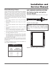
Ignition and Control Timings
Proven Pilot Hot Surface Ignition System F9 is standard on
models 495,000 through 2,065,000 Btu/hr and M9 is optional
on models 495,000 through 2,065,000 Btu/hr with One Hot
Surface Ignition Module.
Hot Surface Ignition Module Timings (Nominal)
Prepurge:
15 Seconds
Hot Surface Igniter Heat-up Time:
25- 35 seconds
Main Burner Flame Establishing Period:
4 Seconds
Failure Response Time:
0.8 Seconds at less than 0.5 µA flame current
Flame Current:
5 - 15 µA
Time Delay Between Stages 1&2:
10 Seconds
Post-purge:
30 Seconds
Pump Delay Timing:
30 Seconds after burner shutdown.
Hydronic Heating Boilers and
Domestic Water Heaters
34