


f. Carefully reinstall combustion chamber door,
jacket panels, dividers, burners, manifolds wires and
hoses. Use new gasket material for proper air seal.
g. Reassemble and test for gas leaks.
h. Cycle appliance and check for proper operation.
An appliance installed in a dust or dirt contaminated
atmosphere will require cleaning of the burners on a 3 to 6
month schedule or more often, based on severity of
contamination. Contaminants can be drawn in with the
combustion air. Non-combustible particulate matter such
as dust, dirt, concrete dust or dry wall dust can block burner
ports and cause non-warrantable failure Use extreme care
when operating an appliance for temporary heat during
new construction. The burners and fan will probably
require a thorough cleaning before the appliance is placed
in service.
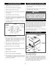
6. Combustion Air Fan: The combustion air fan should be
checked every 6 months. Clean as required when
installed in a dust or dirt contaminated location.
7. Water Circulating Pump: Inspect pump every 6 months
and oil as necessary. Use SAE 30 non-detergent oil or
lubricant specified by pump manufacturer.
8. Keep appliance area clear and free from combustible
materials, gasoline and other flammable vapors and
liquids.
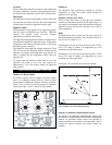
9. Check frequently to be sure the flow of combustion and
ventilation air to the boiler is not obstructed.
Operating Temperature Control
Locating Temperature Control
Remove the control panel door on the front of the appliance
in order to locate and access the temperature control.
Temperature Control Settings
There are three setting knobs on the temperature control
unless your appliance is specified as a boiler only with an
outdoor air reset option. If your appliance is a boiler only
with an outdoor air reset option, there are additional
controls for this option. They are explained under Outdoor
Air Reset Option, page 7.
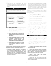
The three setting knobs on the temperature control are for
Set point, Differential, and High-Fire Offset (see Figure 5).
FIG. 5 Temperature Control
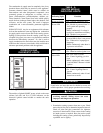
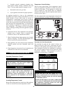
Maximum Set Point Determination
The maximum set point for the control is factory set.
Boilers can be set to 240°F max., water heaters are set to
190°F max., and specialty state and local codes to 200°F.
These maximum set points are established by cutting the
OJ1 and OJ2 jumpers located on the right side of the
temperature controller. The maximum set point is
determined as shown below in TABLE-B.
6
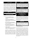
TEMPERATURE ADJUSTMENT
The temperature controller is pre-set at the factory
with test settings. You may need to adjust the
settings to meet your specific needs.
NOTE:
Return water temperatures must not be less than
140°F. If lower return water temperatures are
required, follow the instructions in the Low
Temperature Bypass Requirements or Three-Way
Valves section(s) in the Installation and Service
Manual.
ƽƽ
WARNING
Max.
OJ1 OJ2 Set Point
Connected Connected 240°F
Cut Connected 190°F
Connected Cut 200°F
Cut Cut 160°F
TABLE B
Maximum Set point Determination
Anytime that OJ1 is the only jumper cut, a new
overlay is required under the Set Point knob on the
temperature controller because the scale has changed
to a maximum of 190°F.
Anytime the OJ2 jumper is cut (with or without OJ1),
a new overlay is required under the Set Point knob on
the temperature controller because the scale has
changed to a maximum of 200°F.
NOTE: