


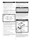


This appliance is supplied with a relief valve(s) sized in
accordance with ASME Boiler and Pressure Vessel Code,
Section IV ("Heating Boilers"). The relief valve(s) is
installed in the vertical position and mounted in the hot
water outlet. No valve is to be placed between the relief
valve, and the appliance. To prevent water damage, the
discharge from the relief valve shall be piped to a suitable
floor drain for disposal when relief occurs. No reducing
couplings or other restrictions shall be installed in the
discharge line. The discharge line shall allow complete
drainage of the valve and line. Relief valves should be
manually operated at least once a year.
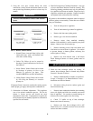
This appliance has five venting options. They are:
1. Conventional Negative Draft Venting
Conventional negative draft venting with vertical
termination.
2. E+ with a Vertical Conventional Vent
E+Vent with a vertical conventional vent for flue
products and a combustion air pipe from either the
sidewall or roof top.
3. Direct Venting with Sidewall Terminations
Direct vent with sidewall terminations for flue
products and combustion air.
4. Direct Venting with Vertical Terminations
Direct vent with vertical through-roof
terminations for flue products and combustion air.
5. Outdoor Installation
Outdoor installation consists of the installation of
a special vent cap / top assembly, gas valve cover,
deflectors, and a weatherproof junction box.
All appliances are shipped from the factory
equipped for conventional negative draft venting.
All other optional vent systems require the
installation of specific vent kits and venting
materials. See the Installation and Service Manual
for a detailed explanation of the installation
requirements for each venting system, components
used and part numbers of vent kits for each model.
Provisions for combustion and ventilation air must be in
accordance with Section 5.3, Air for Combustion and
Ventilation, of the latest edition of the National Fuel Gas
Code, ANSI Z223.1, in Canada, the latest edition of CGA
Standard B149 Installation Code for Gas Burning
Appliances and Equipment, or applicable provisions of the
local building codes.
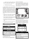
E+ Vent and Direct Vent Units
These optional venting systems use two pipes, one pipe to
exhaust flue products and one pipe to supply combustion
air directly to the appliance. The optional vent systems
have specific material and installation requirements. The
combustion air pipe for the optional vent systems may
terminate horizontally with a sidewall air inlet or vertically
with a rooftop air inlet, based on the venting system
installed. A detailed explanation of the installation
requirements for each venting system, components used
and part numbers of vent kits for each model is included in
the Installation and Service Manual. No additional
combustion air openings are required for the mechanical
room when the optional two pipe venting systems are
properly installed.
3
RELIEF VALVE
ƽƽ
CAUTION
Avoid contact with hot discharge water.
VENT SYSTEM OPTIONS
IMPORTANT:
Examine the venting system at least once a year.
Check all joints and vent pipe connections for
tightness. Also check for corrosion or
deterioration. Immediately correct any problems
observed in the venting system.
ƽƽ
WARNING
Using other vent or air intake materials, failure
to properly seal all seams and joints or failure to
follow vent pipe manufacturer's instructions can
result in personal injury, death or property
damage. Mixing of venting materials will void
the warranty and certification of the appliance.
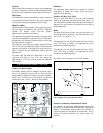
COMBUSTION AND VENTILATION AIR
REQUIREMENTS FOR
CONVENTIONALLY VENTED
APPLIANCES
ƽƽ
CAUTION
Under no circumstances should the equipment room
ever be under a negative pressure. Particular care
should be taken where exhaust fans, attic fans, clothes
dryers, compressors, air handling units, etc., may take
away air from the unit.