


10
NOTE: DIAGRAMS & ILLUSTRATIONS ARE NOT TO SCALE.
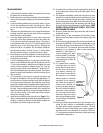
5. If required, install the Outside Air Kit (P/N 71112) as per
the following instructions. To locate the hole in the hearth
for outside air mark and cut a 4” (102 mm) hole in the
hearth. The hole’s center should be 3” (76 mm) directly
forward from the center of the flue outlet or locate as per
the following instructions.
6. Position the stove on your floor protection in the exact
location where it is to be located, making sure all minimum
clearances are met. Mark the floor protection where the
pedestal will be located, then remove the stove.
7. Make four 1-1/2” (38 mm) cuts in one end of the corru-
gated tube and fold the flaps back. Cut a 4” (102 mm) hole
through the floor protection and the floor and insert the
corrugated tube into the hole. Cover it with the supplied
screen and fasten it to the floor protector.
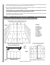
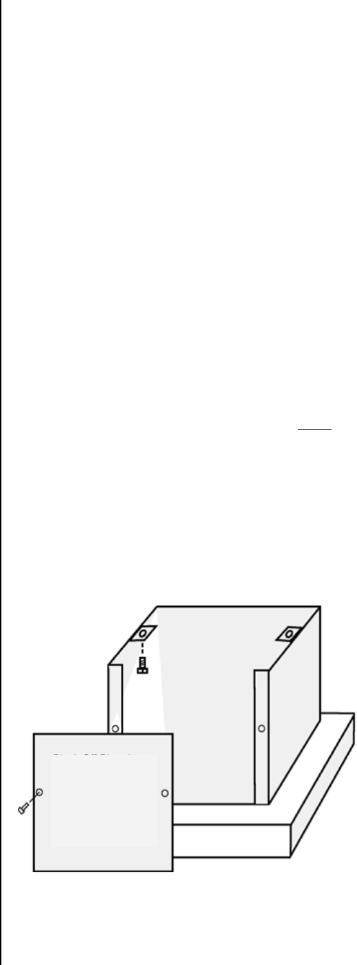
8. Locate the 11-1/2” x 14” (292 mm x 356 mm) metal plate
and paint to match the stove if necessary. Position this
piece so that the 14” (356 mm) dimension evenly overlaps
the lips on the back of the pedestal (see drawing below).
Attach this plate to the back of the pedestal with the self-
tapping screws supplied.
9. If the stove is to be fastened to the floor, attach the stove
with the supplied lag bolts, through the pedestal base
on opposite sides, attaching them into the floor beneath
the floor protection. Seal any irregularities with silicone
sealer.
10. If installed in a mobile home, the heater shall be grounded
to the chassis with a #8 AGW copper wire or equivalent.
11. Install bricks as per instructions on Page 11. It is highly
recommended that the baffle be assembled before the
chimney is installed so that the ceramic fiber blankets can
be adjusted into place from the flue outlet.
12. Install chimney as per manufacturer’s instructions.
Pedestal Installation
(For ash drawer pedestal see instructions included with pedes-
tal)
Residential and Mobile Homes
(Bolting down and grounding are required only in mobile
homes)
CAUTION: Wear gloves during installation in case of
sharp edges on the stove.
1. Remove the heater from the carton, if packaged, upon
receipt and check for any damaged or missing parts.
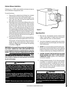
2. Carefully put the stove on pedestal with the open end of
the pedestal facing the rear. DO NOT LEAVE THE
STOVE UNATTENDED UNTIL IT IS BOLTED SECURELY TO
THE PEDESTAL.
3. Line up the holes in the brackets on the pedestal with the
threaded holes in the bottom of the stove. Use the two 1/2”
long bolts and 3/8” standard washers to bolt the stove to
the pedestal. Be sure to see that the stove is mounted
squarely on the pedestal before tightening the two bolts
securely.
4. When installing a pedestal on this stove you MUST plug
the four leg mounting bolt holes, located on the bottom of
the stove in the four corners, with the bolts that were used
to mount the shipping legs. The two rear bolts should not
be installed more than two full rotations to prevent lift-
ing the bricks off the bottom of the stove. FAILURE TO
INSTALL THESE FOUR BOLTS PROPERLY WILL RESULT
IN REDUCED CONTROL OF THE STOVE’S COMBUSTION
SYSTEM!
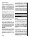
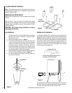
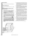
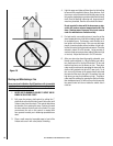
Block Off Plate is
Required When
Installing Outside
Air Into Unit (Plate is
Included With Kit #
OAK-P)
Figure 5