


8
220231 B IMAGE 8
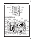
Entry System Mounting
The AE-2000 cabinet is designed to be mounted three ways:
• The unit can be mounted directly to a wall or fl at surface.
• The unit can be mounted recessed into the wall.
• The unit can be mounted on a standard gooseneck pedestal.
Choose a well lit location near the controlled opening. Wiring access for
power, telephone, earth ground, control output must be available to the
mounting location. If the optional remote accessories are used, wiring
access for these cables must also be available to the mounting location.
Opening and Closing the Cabinet
The AE-2000’s cabinet hinges are spring loaded to help weather seal
the cabinet. To open the cabinet, press the cabinet door fi rmly around
each lock while turning each key counterclockwise. To close the cabinet,
press the cabinet door fi rmly around each lock while turning each key
clockwise.
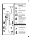
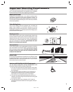
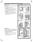
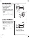
Mounting Preparation
Before mounting the system, the main circuit board mounting plate
must be removed to provide access for the wiring hole and mounting
fasteners.
✦ CAUTION!: Touch a grounded object before proceeding to
discharge static electricity from your body.
1. Carefully remove the fi ve main circuit board wiring connectors:
• The CPU/interface ribbon cable connector.
• The processor module power connector.
• The telephone interface connector.
• The tamper switch connector.
• The keypad power connector.
2. Remove the nut from the Earth Ground stud and remove the green
ground wire lug from the stud.
3. Remove the two bottom circuit board mounting plate nuts.
4. Loosen the two top circuit board mounting plate nuts.
5. Carefully lift up on the mounting plate, removing the circuit board
mounting plate. Set it aside in a safe place.
Reverse these steps to replace the circuit board mounting plate after the
cabinet mounting is complete.
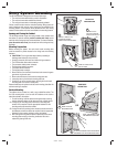
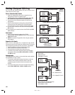
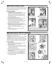
Surface Mounting
The cabinet can be mounted on a wall or any suitable fl at surface. The
four 3/8” mounting holes or the four self-drill locations can be used to
attach the cabinet to the surface.
1. For wall mounting, hold the cabinet at the approximate mounting
location where the display will be about eye level or slightly above.
2A. If using the 3/8” mounting holes, mark the four mounting hole
centers. Drill as required. Use the appropriate fasteners for the
mounting surface to secure the cabinet.
2B. If using the self-drill mounting holes, choose the correct size bit for
the fasteners and drill the cabinet as required. Use the appropriate
fasteners for the mounting surface to secure the cabinet.
3. After routing the wiring into the cabinet, replace the circuit board
mounting plate and plug in the wiring connectors. Be sure to
replace the green ground wire.
MARK THE FOUR
MOUNTING HOLES
ATTACH THE CABINET WITH APPROPRIATE
HARDWARE FOR THE MOUNTING SURFACE
DRILL THE CABINET AT THE
PRE-MARKED LOCATIONS
OR
SURFACE
MOUNTING
1
2
CAREFULLY REMOVE THE
FIVE WIRING HARNESS
CONNECTORS & GROUND WIRE
LOOSEN THE TOP
TWO NUTS & REMOVE
THE BOTTOM TWO NUTS
CAREFULLY REMOVE THE
CIRCUIT BOARD
MOUNTING
PREPARATION
GROUND WIRE STUD
1
2
3