


13
Optional Color CCTV Camera
Linear’s Model CCM-1 (P/N ACP00904) CCTV camera can be installed
inside the AE-2000 Entry System. The camera provides a video signal for
viewing the area in front of the entry system.
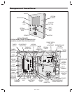
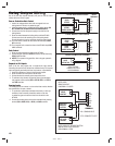
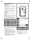
The CAMERA connector is used to connect the camera to the AE-2000.
The 4-conductor cable routes power to, and video from the camera.
The VIDEO jack is the camera output for connection to a video cable with
a Type “BNC” connector. Up to 400 feet of 75-ohm RG-59 video cable can
be used. Longer cable runs may require the use of a video amplifi er.
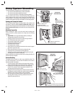
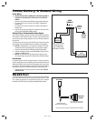
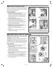
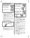
Camera Installation
1. Remove the two plate locknuts from the camera mounting studs
above the right keylock on the AE-2000 faceplate.
2. Remove the cover plate.
3. Remove the protective backing from the plastic window included
with the camera and install the plastic window onto the studs with
the adhesive side against the door.
4. Remove the lens cap from the camera.
5. Mount the camera assembly on the two studs, with the alignment
hole in the camera bracket towards the top. Secure the camera
with the two locknuts.
6. Connect the camera’s cable to the AE-2000’s CAMERA connector.
7. Connect the video cable to the AE-2000’s VIDEO connector.
8. Connect the other end of the video cable to the viewing monitor or
the video distribution system.
220231 B IMAGE 13
Optional Postal Lock
A postal lock can be installed in the AE-2000 Entry System to provide
keyed access for the postal service. The AE-2000 case is designed to
accept a U.S. Postal Service postal lock. When the postal lock is engaged,
the programmed output relay will activate.
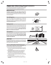
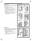
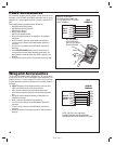
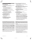
Postal Lock Installation
1. After opening the cabinet, re-lock the left cabinet lock to provide
clearance to remove the postal lock switch plate.
2. Remove the four locknuts that retain the postal lock switch plate,
hole cover plate, and block (below the left cabinet lock on the
AE-2000 faceplate). The hole cover plate and block will not be
used and can be discarded.
3. Remove the switch plate from the four studs.
4. Install the postal lock assembly onto the four studs. The postal
lock’s moving plunger should point down (see fi gure).
5. Replace the postal lock switch plate with the microswitch oriented
toward the front of the cabinet where it will be pressed by the
postal lock’s moving plunger (see fi gure).
6. Secure the postal lock and switch plate with the four locknuts.
✦ NOTE: Be sure the postal lock’s plunger actuates the
microswitch. Adjust the switch plate and the postal lock then test
the action until the microswitch fully actuates.
7. Tighten the four locknuts after the adjustment and testing is
complete.
8. When programming the system, set the postal lock option to
activate the desired relay output.
REMOVE LOCKNUTS
REMOVE PLATE
INSTALL POSTAL LOCK
REPLACE PLATE WITH THE
MICROSWITCH TOWARDS
THE FRONT OF THE CABINET,
REPLACE LOCKNUTS
NOTE: BE SURE THE POSTAL LOCK'S PLUNGER ACTUATES THE
MICROSWITCH. ADJUST THE SWITCH PLATE AND THE POSTAL LOCK
THEN TEST THE ACTION UNTIL THE MICROSWITCH FULLY ACTUATES
4
3
2
1
PLUNGER
POINTS
DOWN
1
REMOVE PLATE RETAINING NUTS
2
3
4
5
6
7
REMOVE THE COVER PLATE
INSTALL THE CLEAR WINDOW REMOVE THE LENS CAP
ATTACH CAMERA WITH TWO NUTS
CONNECT
CAMERA
WIRING
HARNESS
CONNECT
VIDEO
CABLE
REMOVE PROTECTIVE
BACKING AND APPLY
WINDOW WITH
ADHESIVE SIDE
AGAINST DOOR