


12
220231 B IMAGE 12
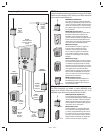
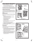
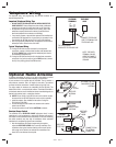
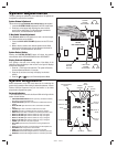
Telephone Wiring
For telephone entry and programming, the AE-2000 connects to a
standard telephone line.
Important Telephone Wiring Tips
• DO NOT ROUTE TELEPHONE AND AC WIRING INSIDE THE
SAME CONDUIT. Route all telephone wires inside a dedicated
conduit that is at least six inches away from any AC line wiring.
• All telephone wiring must be made on the “building” side of the
telephone company’s demarcation device (the terminal block
where the telephone line connects to the building).
• If any security system or personal alert system at the installation is
connected to the telephone line, be sure that it is connected to the
line ahead of the AE-2000 using a RJ-31X or RJ-38X interface.
• Use only high-quality telephone wire. All telephone wire should be
twisted-pair with a minimum size of 24 AWG.
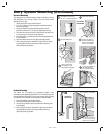
Typical Telephone Wiring
1A. If using the AE-2000 modular connector for the telephone
connection, connect a double-ended modular cable between the
AE-2000’s PHONE jack and the modular telephone jack wired to
the installation’s telephone line.
1B. If using the AE-2000 terminal block for the telephone connection,
connect the “ring” wire (usually red) to the RING terminal, connect
the “tip” wire (usually green) to the TIP terminal.
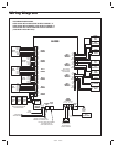
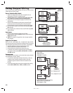
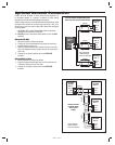
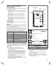
Optional Radio Antenna
If wireless transmitters are going to be used in the system a remote
antenna must be installed to provide reception for the AE-2000.
A basic antenna kit is supplied with the AE-2000. The kit contains a
whip antenna, connector, and a 36” length of coax cable. The antenna
connector should be mounted on a metal surface using a 3/8” hole.
Two other models of antennas are compatible with the AE-2000. The
Model EXA-1000 is a non-directional antenna. The Model EXA-2000 is
a directional antenna used in installations where transmitted signals are
desired to be received only in a particular direction.
✦ NOTE: Up to 50 feet of type RG-59 coax can be used to connect
the antenna to the AE-2000. Keep the coax as short as possible.
1. Install the antenna. (See installation instructions if using the
EXA-1000 or EXA-2000.)
2. Connect the antenna coax cable to the antenna and route the
cable to the AE-2000.
3. Connect the cable to the AE-2000’s ANTENNA connector.
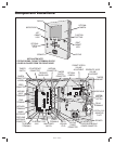
Receiver Range Control
The AE-2000 has a RECEIVER RANGE adjustment knob. In some
installations, it may be necessary to reduce the effective radio range of
the receiver to limit the distance that transmitters can be used. Reducing
the radio’s sensitivity may also help in installations where unwanted
interference is overpowering signals from transmitters.
1. After the installation and system programming is complete,
adjust the RECEIVER RANGE knob to suit the installation. Test
transmitters from typical locations that they will be used. Set the
radio range so the receiver can activate from transmitters from
about 25% more distance than required.
TELEPHONE
TERMINALS
EARTH
RING
TIP
TELEPHONE
JACK
TO THE INCOMING
DEDICATED TELEPHONE LINE
CONNECT TELEPHONE
LINE TO TERMINALS OR
TELEPHONE JACK
NOTE: THE EARTH
TERMINAL CAN BE
USED TO CONNECT
TO THE TELEPHONE
GROUND
RECEIVER
RANGE
KNOB
AE-2000
CIRCUIT BOARD
CONNECT COAX
TO ANTENNA
CONNECTOR
RECEIVER
TEST POINT
OPTIONAL
EXA-2000
DIRECTIONAL
ANTENNA
OPTIONAL EXA-1000
OMNI-DIRECTIONAL
ANTENNA
SUPPLIED
ANTENNA
KIT
CONNECTOR
36" COAX
WHIP
ANTENNA