


A-4
INSTALLATION
POWER WAVE 455
A-4
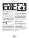
VOLTAGE SENSING AT THE
WORKPIECE
A four-pin work piece voltage sense lead connector is
located beneath the output stud cover. The use of a
work piece sense lead is optional for most welding
modes, but may be used if desired.
Sense Lead Kits (K490-10, -25 or -50) are available
for this purpose.
To enable the work piece voltage sensing lead, a
jumper must be removed from the Control PC Board
as follows:
1) Turn the Power Wave 455 power OFF.
2) Remove the front nameplate from the Power Wave
455 by removing the six screws from the name-
plate. Save the screws for re-use.
3) Locate P26, located on the upper right edge of the
Control PC Board. It is a 16 pin connector with
only two wires going into it. Unplug P26. It should
remain attached to the main harness.
4) Install the front nameplate on the Power Wave 455
by replacing the six screws saved in Step 2.
5) Plug a Sense Lead into the Sense Lead
Receptacle. Note: Only the lead marked ‘WORK’
is used. The lead marked ‘ELECT’ can be cut off
and discarded.
6) Connect the WORK sense lead clamp to the piece
being welded.
The Power Wave 455 will now use the external work
piece Sense Lead to sense arc voltage in all welding
modes. If the Sense Lead is enabled but not connect-
ed to the work piece, extremely high welding output
currents may result.
To restore normal work piece sensing (at the output
terminals) reconnect P26 to the Control PC board.
The Sense Lead can then be disconnected.
POWER WAVE / POWER FEED WIRE
FEEDER INTERCONNECTIONS
ELECTRODE & WORK LEADS —
ELECTRODE POSITIVE APPLICATIONS
Most welding applications run with the electrode being
positive (+). For those applications, connect the elec-
trode cable between the wire feeder and the positive
(+) output stud on the power source (located beneath
the spring loaded output cover near the bottom of the
case front).
A work lead must be run from the negative (-) power
source output stud to the work piece. The work piece
connection must be firm and secure, especially if
pulse welding is planned. Excessive voltage drops at
the work piece connection often result in unsatisfacto-
ry pulse welding performance.
ELECTRODE & WORK LEADS —
ELECTRODE NEGATIVE APPLICATIONS
When negative electrode polarity is required, such as
in some Innershield™ applications, install as above,
except reverse the output connections at the power
source (electrode cable to the negative (-) stud, and
work cable to the positive (+) stud).
CONTROL CABLE CONNECTIONS
Connect the control cable between the wire feeder
and power source. The power source wire feeder
connection is located under the spring loaded output
cover, near the bottom of the case front. The control
cable is keyed and polarized, so it can be installed in
only one way.
For neatness and convenience sake, both the elec-
trode and control cables can be routed behind the left
or right strain reliefs (under the spring loaded output
cover), and along the channels formed into the base
of the Power Wave, out the back of the channels, and
then to the wire feeder.