


A-3
INSTALLATION
POWER WAVE 455
A-3
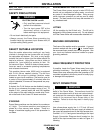
INPUT FUSE AND SUPPLY WIRE
CONSIDERATIONS
Refer to the Technical Specifications at the beginning
of this Installation section for recommended fuse and
wire sizes. Fuse the input circuit with the recommend-
ed super lag fuse or delay type breakers (also called
“inverse time” or “thermal/magnetic” circuit breakers).
Choose an input and grounding wire size according to
local or national electrical codes. Using fuses or cir-
cuit breakers smaller than recommended may result in
“nuisance” shut-offs from welder inrush currents, even
if the machine is not being used at high currents.
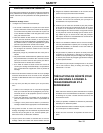
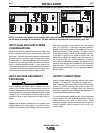
INPUT VOLTAGE RECONNECT
PROCEDURE
Only a qualified electrician should connect the input
leads to the Power Wave. Connections should be
made in accordance with all local and national electri-
cal codes and the connection diagram located on the
inside of the reconnect/input access door of the
machine. Failure to do so may result in bodily injury or
death.
------------------------------------------------------------------------
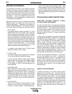
Welders are shipped connected for the highest input
voltage listed on the rating plate. To move this con-
nection to a different input voltage, refer to reconnect
instructions located on the inside of the input access
door or in Figure A.1. If the main reconnect switch is
placed in the wrong position, the welder will not pro-
duce output power. If the Auxiliary (“A”) lead is placed
in the wrong position, there are two possible results.
If the lead is placed in a position higher than the
applied line voltage, the welder may not come on at
all. If the Auxiliary (“A”) lead is placed in a position
lower than the applied line voltage, the welder will not
come on, and the two circuit breakers in the reconnect
area will open. If this occurs, turn off the input volt-
age, properly connect the “A” lead, reset the breakers,
and try again.
OUTPUT CONNECTIONS
Use the largest welding (electrode and ground) cables
possible — at least 2/0, 4/0 preferred, copper wire —
even if the average output current would not normally
require it. When pulsing, the pulse current can
exceeds 650 amps. Voltage drops can become
excessive, leading to poor welding characteristics, if
undersized welding cables are used.
To avoid interference problems with other equipment
and to achieve the best possible operation, route all
cables directly to the work or wire feeder. Avoid
excessive lengths, bundle the electrode and ground
cables together where practical, and do not coil
excess cable.
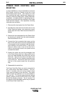
FIGURE A.1 - CONNECTION DIAGRAM ON RECONNECT/INPUT ACCESS DOOR
200-208V
220-230V
380-415V
440-460V
200-208V
220-230V
VOLTAGE=220-230V
220-230V
200-208V
220-230V
380-415V
440-460V
200-208V
U / L1
440-460V
380-415V
.
inspecting or servicing machine.
Do not operate with covers
.
removed.
Do not touch electrically live parts.
.
Only qualified persons should install,
use or service this equipment.
.
’A’
’A’
VOLTAGE=380-415V
’A’
S23847
VOLTAGE=200-208V
THE LINCOLN ELECTRIC CO. CLEVELAND, OHIO U.S.A.
A
’A’
VOLTAGE=440-460V
CR1
W / L3
V / L2
380-415V
440-460V
Disconnect input power before
INPUT SUPPLY CONNECTION DIAGRAM
NOTE: Turn main input power to the machine OFF before performing reconnect procedure. Failure to do
so will result in damage to the machine. DO NOT switch the reconnect bar with machine power ON.
WARNING
S24196
THE LINCOLN ELECTRIC CO. CLEVELAND, OHIO U.S.A.
550-575V
VOLTAGE=440-460V VOLTAGE=550-575V
’A’ ’A’
A
440-460V
.
inspecting or servicing machine.
U / L1
Disconnect input power before
.
Do not operate with covers
removed.
V / L2
.
Do not touch electrically live parts.
CR1
W / L3
INPUT SUPPLY CONNECTION DIAGRAM
.
use or service this equipment.
Only qualified persons should install,
440-460V
550-575V