


8
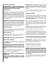
NOTE: DIAGRAMS & ILLUSTRATIONS ARE NOT TO SCALE.
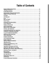
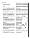
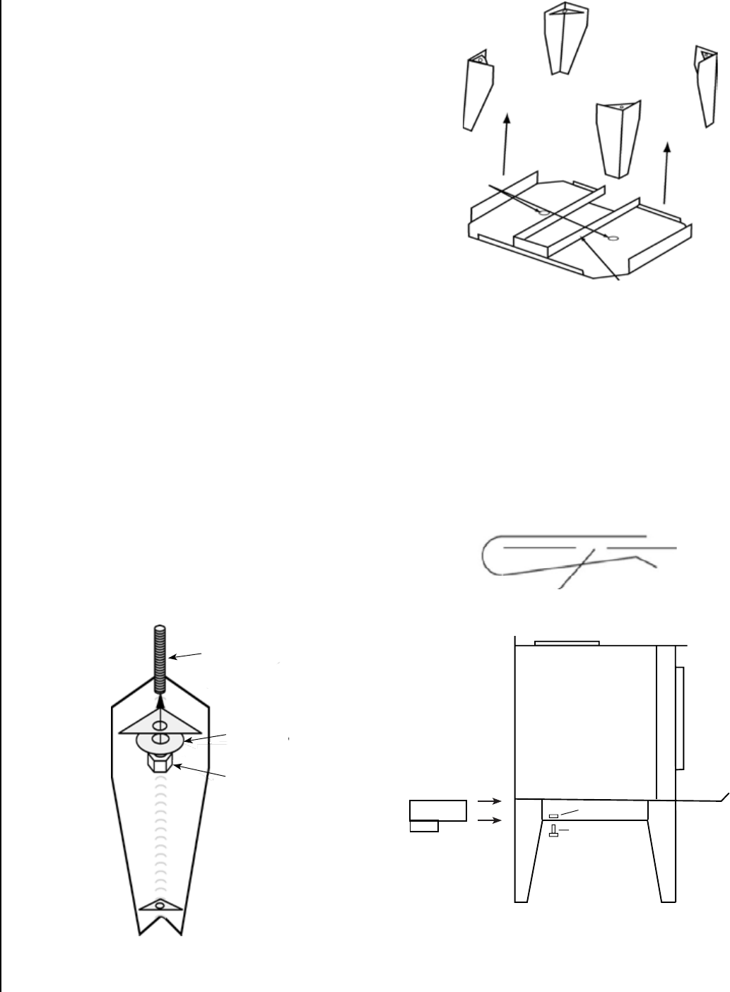
Heat Shield
Mounting Holes
Air Channel
Front
Figure 2
Figure 1
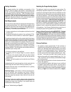
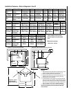
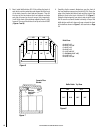
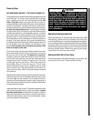
Outside Air Kit Installation
To install the “Outside Air Kit,” position the clip so that the nut is
directly above the hole punched in the back of the heatshield (See
Figure 3). Install the outside air adapter box on the stove by slid-
ing it into the air channel located between the bottom heatshield
and the stove bottom until the oblong ring is approximately 1/4”
from the rear edge of the lower heatshield. Make sure the ring is
facing down. Thread the 1/4” bolt up through the nut in the clip
until snug against the adapter box.
To locate the hole in the hearth for outside air, mark a 4” circle on
the hearth. The circle’s center should be 2-3/4” directly back from
the center of the flue outlet and 5/8” to the left side.
Figure 3
Expanded View of Clip
Leg and Heatshield Installation
Note: The threaded rods used to bolt the legs to the stove are
packaged with the heatshield, as a heatshield is required when
a stove is installed on legs.
Residential and Mobile Homes
(Bolting down and grounding of stove are required only in
mobile homes).
Open all cartons, if any and remove the contents upon receipt
and check for any damaged or missing parts. If there is hidden
damage, notify your freight company or Lennox Hearth Products
dealer immediately.
CAUTION: Wear gloves during installation in case of
sharp edges on the stove.
Leg Installation
1. Carefully place stove on its back. Be careful not to scratch
the stove, use a piece of cardboard or carpet to protect
the back of the stove.
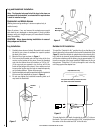
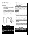
2. Mount all four legs as shown in Figure 1.
3. First, screw the threaded rods into the holes at the four
corners on the bottom of the stove. Screw the threaded
rods into the firebox three full rotations or 3/16 to 1/4”
(if the rear rods are screwed in too far they will lift the
bricks off the bottom of the stove). Use a washer and nut
to secure the leg. Be sure the legs are mounted squarely
on the firebox bottom. Tighten nuts securely.
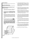
4. Use the two bolts and washers provided with the heatshield
kit to mount the heatshield as shown in Figure 2.
5. Do not over tighten the heatshield mounting bolts as it
may bend the heatshield.
Line up the hole in the clip with the hole in the
rear center of the bottom heatshield
Clip
1/4” Bolt
Threaded
Rod
Washer
Nut