


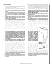
7
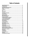
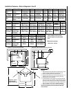
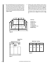
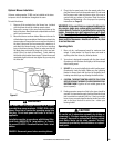
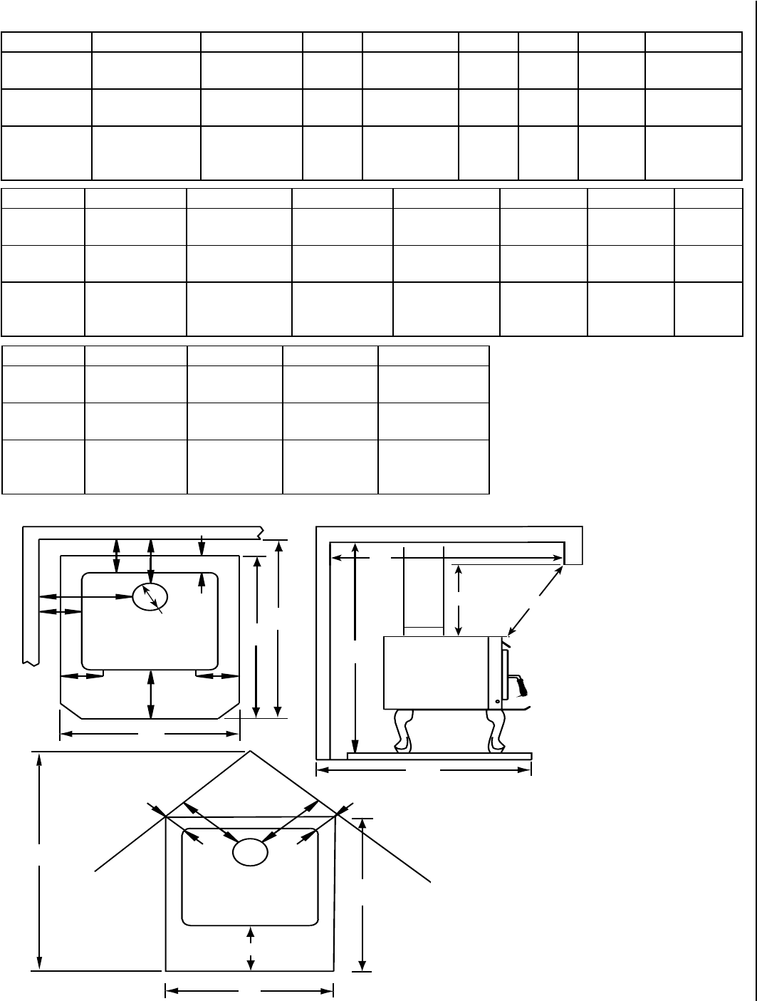
Diagram B: Side View-Alcove & Parallel Installation
Diagram A: Top View-Parallel Installation
K
B
A
E
C
D
*L
K
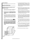
Floor Protection
Floor Protection
Floor Protection
G G
F F
72" Min.
H
I
M
J
I
J
H
†
E
†
E
L
48”
Maximum
Depth
Diagram C: Top
View-Corner
Installation
N
P
T
Installation Clearances - Refer to Diagrams A, B and C
PIPE INSTALLATION A
B (1)
C
D (1)
E†
F (1,4)
G (4)
6” Single
Wall
Residential or
Alcove
USA-16”
CAN-483mm
14”
356mm
USA-21”
CAN-610mm
12-1/2”
318mm
8”
200mm
9-3/4”
248mm
USA-18”
CAN-533mm
6” Single w/
Pipe Shield
Residential or
Alcove
USA-10”
CAN-330mm
8”
200mm
USA-18”
CAN-533mm
9-1/2”
241mm
8”
200mm
5-1/2”
140mm
USA-13-1/2”
CAN-419mm
6” Double
Wall
Residential or
Alcove or Mobile
Home*
USA-10”
CAN-330mm
8”
200mm
USA-18”
CAN-533mm
9-1/2”
241mm
8”
200mm
5-1/2”
140mm
USA-13-1/2”
CAN-419mm
PIPE INSTALLATION
H (2) I (6) J (2) K L (5)
M
Single Wall Residential or
Alcove
USA-33-3/4”
CAN-1111mm
USA-47-3/4”
CAN-1340mm
USA-33-1/2”
CAN-1003mm
USA-16”
CAN-450mm
USA 0"
CAN-200mm
84”
2134mm
Single w/
Pipe Shield
Residential or
Alcove
USA-33-3/4”
CAN-1111mm
USA-41-3/4”
CAN-1188mm
USA-33-1/2”
CAN-1003mm
USA-16”
CAN-450mm
USA 0"
CAN-200mm
84”
2134mm
Double Wall
Air-Cooled
Residential or
Alcove or Mo-
bile Home*
USA-33-3/4”
CAN-1111mm
USA-41-3/4”
CAN-1188mm
USA-33-1/2”
CAN-1003mm
USA-16”
CAN-450mm
USA 0"
CAN-200mm
72”
1829mm
† USA=8" (200mm) from door opening,
Canada=8" (200mm) from sides and back
of unit
u
Dimensions to Stove Body
* Mobile Home - USA only
PIPE INSTALLATION Nu Pu
T (6)
Single Wall Residential or
Alcove
30"
762mm
36"
914mm
USA-58-1/2”
CAN-1645mm
Single w/
Pipe Shield
Residential or
Alcove
30"
762mm
36"
914mm
USA-52”
CAN-1486mm
Double Wall
Air-Cooled
Residential or
Alcove or Mo-
bile Home*
30"
762mm
36"
914mm
USA-52”
CAN-1486mm
Footnotes:
1- These dimensions to the stove body are for reference only. Actual
distances should be measured from the stove’s flue collar.
2-
Minimum noncombustible hearth pad dimensions.
3- Shield shall be attached to the rear of the stove pipe with a 1” air
space and must run from the top of the stove to the ceiling.
4- Not applicable to alcove installations.
5- In corner applications, when installed at minimum back wall clear-
ances, the required floor protection is dimensioned off the back
plane of the stove, therefore the floor protection required off the
back corners (at a 45 degree angle) only needs to extend to the
wall. This situation will only occur in CANADA installations.
6- Reference dimension only, to assist in planning the installation.
Clearances to connector pipe shall be measured from the flue
collar of the stove.
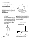
Diagram C: Top View -
Corner Clearance,
Stove and Flue to Wal
l
6” Ø
Flue Collar