


Page 40
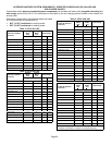
Two−Stage Modulation Compressors
Checks
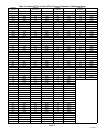
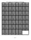
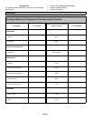
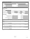
Use this checklist on page 42 to verify part-load and
full-load capacity operation of two-stage modulation
compressors.
TOOLS REQUIRED
S Refrigeration gauge set
S Digital volt/amp meter
S Electronic temperature thermometer
S On-off toggle switch
IMPORTANT
This performance check is ONLY valid on systems that
have clean indoor and outdoor coils, proper airflow over
coils, and correct system refrigerant charge. All
components in the system must be functioning proper to
correctly perform compressor modulation operational
check. (Accurate measurements are critical to this test
as indoor system loading and outdoor ambient can affect
variations between low and high capacity readings).
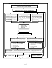
PROCEDURE
NOTE − Block outdoor coil to maintain a minimum of 375
psig during testing).
1. Turn main power OFF to outdoor unit.
2. Adjust room thermostat set point 5ºF above the room
temperature.
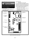
3. Remove control access panel. Install refrigeration
gauges on unit. Attach the amp meter to the common
(black wire) wire of the compressor harness. Attach
thermometer to discharge line as close as possible to
the compressor.
4. Turn toggle switch OFF and install switch in series with
Y2 wire from room thermostat.
5. Cycle main power ON.
6. Allow pressures and temperatures to stabilize before
taking measurements (may take up to 10 minutes).
7. Record all of the readings for the Y1 demand.
8. Close switch to energize Y2 demand. Verify power is
going to compressor solenoid.
9. Allow pressures and temperatures to stabilize before
taking measurements (may take up to 10 minutes).
10. Record all of the readings with the Y1 and Y2 demand.
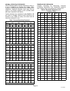
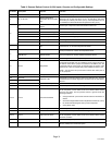
11. If temperatures and pressures change in the direction
noted in Two−Stage Modulation Compressor Field
Operational Checklist on page 42, the compressor is
properly modulating from low to high capacity. (If no
amperage, pressures or temperature readings
change when this test is performed, the compressor
is not modulating between low and high capacity and
replacement is necessary).
12. After testing is complete, return unit to original set up.
Maintenance
DEALER
Maintenance and service must be performed by a qualified
installer or service agency. At the beginning of each
cooling season, the system should be checked as follows:
Outdoor Unit
1. Clean and inspect outdoor coil (may be flushed with a
water hose). Ensure power is off before cleaning.
2. Outdoor unit fan motor is pre−lubricated and sealed.
No further lubrication is needed.
3. Visually inspect all connecting lines, joints and coils for
evidence of oil leaks.
4. Check all wiring for loose connections.
5. Check for correct voltage at unit (unit operating).
6. Check amp draw on outdoor fan motor.
Motor Nameplate:_________ Actual:__________.
7. Inspect drain holes in coil compartment base and
clean if necessary.
NOTE - If insufficient heating or cooling occurs, the unit
should be gauged and refrigerant charge should be
checked.
Outdoor Coil
It may be necessary to flush the outdoor coil more
frequently if it is exposed to substances which are
corrosive or which block airflow across the coil (e.g., pet
urine, cottonwood seeds, fertilizers, fluids that may contain
high levels of corrosive chemicals such as salts)
S Outdoor Coil Ċ The outdoor coil may be flushed with
a water hose.
S Outdoor Coil (Sea Coast) Ċ Moist air in ocean
locations can carry salt, which is corrosive to most
metal. Units that are located near the ocean require
frequent inspections and maintenance. These
inspections will determine the necessary need to wash
the unit including the outdoor coil. Consult your
installing contractor for proper intervals/procedures
for your geographic area or service contract.
Indoor Unit
1. Clean or change filters.
2. Lennox blower motors are prelubricated and
permanently sealed. No more lubrication is needed.
3. Adjust blower speed for cooling. Measure the pressure
drop over the coil to determine the correct blower CFM.
Refer to the unit information service manual for pressure
drop tables and procedure.
4. Belt Drive Blowers − Check belt for wear and proper
tension.
5. Check all wiring for loose connections.
6. Check for correct voltage at unit. (blower operating)
7. Check amp draw on blower motor.
Motor Nameplate:_________ Actual:__________.