


Page 33
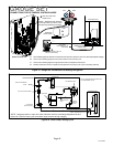
XP16 SERIES
High Pressure Switch (S4)
When the high pressure switch trips, the demand defrost
control will cycle off the compressor, and the strike counter
in the demand defrost control will count one strike. High
Pressure (auto reset) − trip at 590 psig, reset at 418.
Low Pressure Switch (S87)
When the low pressure switch trips, the demand defrost
control will cycle off the compressor, and the strike counter
in the demand defrost control will count one strike. Low
pressure switch (auto reset) − trip at 25 psig, reset at 40
psig.
The low pressure switch is ignored under the following
conditions:
S During the defrost cycle and 90 seconds after the
termination of defrost
S When the average ambient sensor temperature is
below 15° F (−9°C)
S For 90 seconds following the start up of the
compressor
S During test mode
Ambient Sensor (RT13)
The ambient sensor considers outdoor temperatures
below −35°F (−37°C) or above 120°F (48°C) as a fault. If the
ambient sensor is detected as being open, shorted or out
of the temperature range of the sensor, the demand
defrost control will not perform demand defrost operation.
The demand defrost control will revert to time/temperature
defrost operation and will display the appropriate fault
code. Heating and cooling operation will be allowed in this
fault condition.
Coil Sensor (RT21)
Coil SensorĊThe coil temperature sensor considers
outdoor temperatures below −35°F (−37°C) or above 120°F
(48°C) as a fault. If the coil temperature sensor is detected
as being open, shorted or out of the temperature range of
the sensor, the demand defrost control will not perform
demand or time/temperature defrost operation and will
display the appropriate fault code. Heating and cooling
operation will be allowed in this fault condition.
High Discharge Temperature Sensor (RT28)
If the discharge line temperature exceeds a temperature of
285°F (140°C) during compressor operation, the demand
defrost control will de−energize the compressor contactor
output (and the defrost output, if active). The compressor
will remain off until the discharge temperature has dropped
below 225°F (107°C) and the 5-minute anti−short cycle
delay has been satisfied. This sensor has two fault and
lockout codes:
1. If the demand defrost control recognizes five high
discharge line temperature faults during a single (Y1)
compressor demand, it reverts to a lockout mode and
displays the appropriate code. This code detects
shorted sensor or high discharge temperatures. Code
on demand defrost control is Discharge Line
Temperature Fault and Lockout.
2. If the demand defrost control recognizes five
temperature sensor range faults during a single (Y1)
compressor demand, it reverts to a lockout mode and
displays the appropriate code. The demand defrost
control detects open sensor or out-of-temperature
sensor range. This fault is detected by allowing the unit
to run for 90 seconds before checking sensor
resistance. If the sensor resistance is not within range
after 90 seconds, the demand defrost control will count
one fault. After five faults, the demand defrost control
will lockout. Code on demand defrost control is
Discharge Sensor Fault and Lockout.
The discharge line sensor, which covers a range of 150°F
(65°C) to 350°F (176°C), is designed to mount on a ½"
refrigerant discharge line.
NOTE − Within a single room thermostat demand, if
5−strikes occur, the demand defrost control will lockout the
unit. demand defrost control 24 volt power R must be
cycled OFF or the TEST pins on demand defrost control
must be shorted between 1 to 2 seconds to reset the
demand defrost control.
Crankcase Heater (HR1) and Crankcase Thermostat
Switch (S40)
The reference models are equipped with a 70 watt, belly
band type crankcase heater. HR1 prevents liquid from
accumulating in the compressor. HR1 is controlled by a
thermostat located on the liquid line. When liquid line
temperature drops below 50° F the thermostat closes
energizing HR1. The thermostat will open, de−energizing
HR1 once liquid line temperature reaches 70° F .
Liquid Line Bi−Flow Filter Drier
The unit is equipped with a large−capacity biflow filter drier
which keeps the system clean and dry. If replacement is
necessary, order another of like design and capacity. The
replacement filter drier must be suitable for use with
HFC−410A refrigerant.
The replacement filter drier must be suitable for use with
HFC−410A refrigerant.
SECOND−STAGE OPERATION
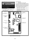
If the demand defrost control (A108) receives a call for
second−stage compressor operation Y2 in heating or
cooling mode and the first-stage compressor output is
active, the second-stage compressor solenoid output will
be energized.
If first-stage compressor output is active in heating mode
and the outdoor ambient temperature is below the selected
compressor lock−in temperature, the second-stage
compressor solenoid output will be energized without the
Y2 input. If the jumper is not connected to one of the
temperature selection pins on P3 (40, 45, 50, 55°F), the
default lock−in temperature of 40°F (4.5°C) will be used.
The demand defrost control de−energizes the
second-stage compressor solenoid output immediately
when the Y2 signal is removed or the outdoor ambient
temperature is 5°F above the selected compressor lock−in
temperature, or the first-stage compressor output is
de−energized for any reason.