Page 34
Defrost System
This section addresses:
S Emergency Heat
S Defrost System Overview
S Defrost Control Connections, Jumper Settings and
Features
S Operational Mode Overview (Calibration, Normal and
Defrost)
S Defrost Cycle Actuation
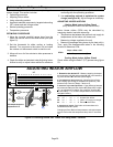
EMERGENCY HEAT (AMBER LIGHT)
An emergency heat function is designed into some room
thermostats. This feature is applicable when isolation of the
outdoor unit is required, or when auxiliary electric heat is
staged by outdoor thermostats. When the room thermostat is
placed in the emergency heat position, the outdoor unit
control circuit is isolated from power and field-provided relays
bypass the outdoor thermostats. An amber indicating light
simultaneously comes on to remind the homeowner that he
is operating in the emergency heat mode.
Emergency heat is usually used during an outdoor unit
shutdown, but it should also be used following a power
outage if power has been off for over an hour and the
outdoor temperature is below 50°F (10°C). System should
be left in the emergency heat mode at least six hours to
allow the crankcase heater sufficient time to prevent
compressor slugging.
DEFROST SYSTEM OVERVIEW
The control monitors ambient temperature, outdoor coil
temperature, and total run time to determine when a
defrost cycle is required. The coil temperature probe is
designed with a spring clip to allow mounting to the outside
coil tubing. The location of the coil sensor is important for
proper defrost operation.
NOTE − The demand defrost control accurately measures
the performance of the system as frost accumulates on the
outdoor coil. This typically will translate into longer running
time between defrost cycles as more frost accumulates on
the outdoor coil before the demand defrost control initiates
defrost cycles.
DEFROST CONTROL CONNECTIONS, JUMPERS
SETTINGS AND FEATURES
Pressure Switch 5−Strike Lockout
The internal control logic of the demand defrost control
counts the pressure switch trips only while the Y1 (Input)
line is active. If a pressure switch opens and closes four
times during a Y1 (Input), the control logic will reset the
pressure switch trip counter to zero at the end of the Y1
(Input). If the pressure switch opens for a fifth time during
the current Y1 (Input), the control will enter a lockout
condition.
The 5−strike pressure switch lockout condition can be reset
by cycling OFF the 24−volt power to the demand defrost
control or by shorting the TEST pins between 1 to 2
seconds. All timer functions (run times) will also be reset.
If a pressure switch opens while the Y1 Out line is
engaged, a 5−minute short cycle will occur after the switch
closes.
Demand Defrost Control Pressure Switch
Connections
The unit’s automatic reset pressure switches (LO PS − S87
and HI PS − S4) are factory−wired into the demand defrost
control on the LO−PS and HI−PS terminals, respectively.
Demand Defrost Control Sensors
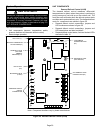
Sensors connect to the demand defrost control through a
field-replaceable harness assembly that plugs into the
demand defrost control as illustrated in figure 1. Through
the sensors, the demand defrost control detects outdoor
ambient, coil, and discharge temperature fault conditions.
As the detected temperature changes, the resistance
across the sensor changes.
Testing Demand Defrost Control Sensors
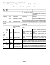
Sensor resistance values can be checked by ohming
across pins shown in table 11.
Table 11. Sensor Temperature /Resistance Range
Sensor
Temperature
Range °F (°C)
Resistance values
range (ohms)
Pins/W
ire
Color
Outdoor −35 (−37) to 120 (48) 280,000 to 3750 3 & 4
(Black)
Coil −35 (−37) to 120 (48) 280,000 to 3750 5 & 6
(Brown)
Discharge (if
applicable)
24 (−4) to 350 (176) 41,000 to 103 1 & 2
(Yellow)
Note: Sensor resistance increases as sensed temperature decreases.
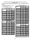
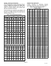
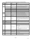
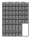
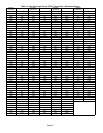
Tables 12 and 13 shows how the resistance varies as the
temperature changes for various types of sensors.
NOTE − When checking the ohms across a sensor, be
aware that a sensor showing a resistance value that is not
within the range shown in table 11, may be performing as
designed. However, if a shorted or open circuit is detected,
then the sensor may be faulty and the sensor harness will
need to be replaced.
Defrost Temperature Termination Jumper
Settings (P1)
The demand defrost control selections are: 50, 70, 90, and
100°F (10, 21, 32 and 38°C). The shunt termination pin is
factory set at 50°F (10°C). If temperature shunt is not
installed, default termination temperature is 90°F (32°C).
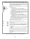
Test Pins (P1) Function
Placing the jumper on the field test pins (P1) allows the
technician to:
S Clear short cycle lockout
S Clear five−strike fault lockout
S Cycle the unit in and out of defrost mode
S Place the unit in defrost mode to clear the coil
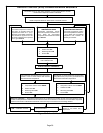
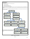
See figure 27 for flowchart of test pin (P1) operations.


