Page 3
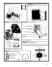
XP16 SERIES
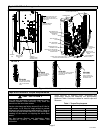
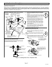
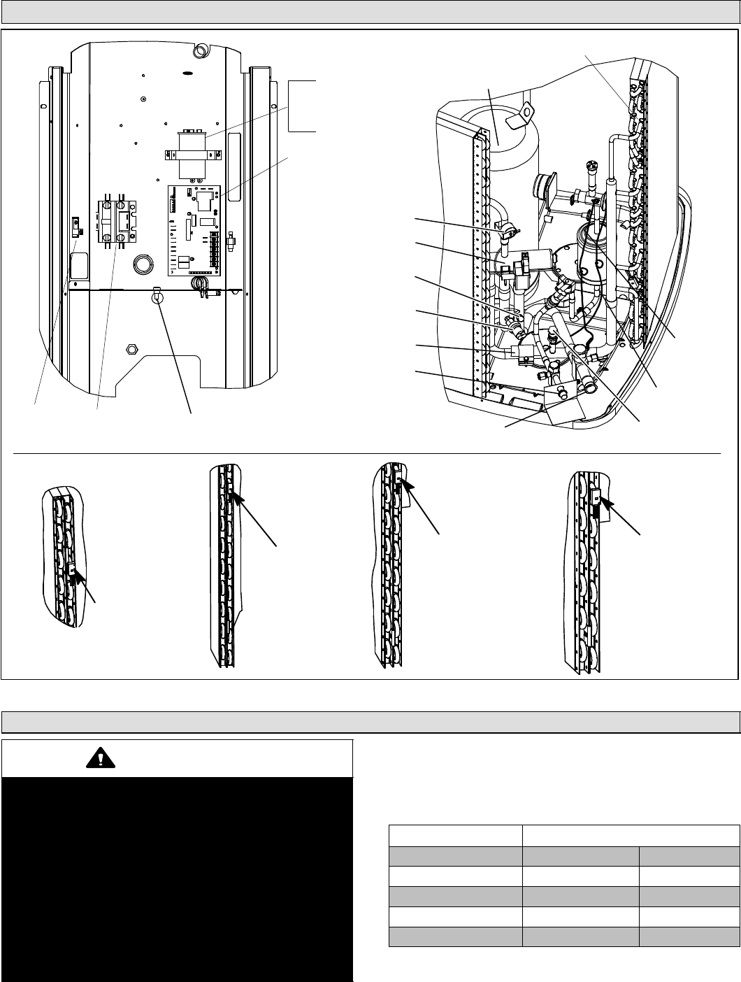
Typical Unit Parts Arrangement
CHECK /
EXPANSION
VALVE
VAPOR VALVE AND GAUGE PORT /
SUCTION LINE CONNECTIONS
EXPANSION VALVE
SENSING BULB
LOW PRESSURE
SWITCH (S87)
LIQUID LINE
BI−FLOW FILTER
DRIER
HIGH PRESSURE
SWITCH (S4)
COMPRESSOR
LIQUID VALVE AND GAUGE
PORT / LIQUID LINE
CONNECTIONS
REVERSING
VALVE (L1)
DEMAND DEFROST
CONTROL (A108)
SINGLE POLE
CONTACTOR
(K1)
GROUND
LUG AMBIENT
TEMPERATURE
SENSOR (RT13)
TRUE SUCTION
PORT
DISCHARGE LINE
SENSOR (RT28)
XP16−024
COIL SENSOR −THIRD
HAIRPIN DOWN FROM
THE TOP ON INSIDE
ROW.
XP16−036
COIL SENSOR − NINTH
HAIRPIN UP FROM THE
BOTTOM ON INSIDE
ROW.
XP16−048
COIL SENSOR − EIGHT HAIRPIN
UP FROM THE BOTTOM ON
INSIDE ROW.
XP16−060
COIL SENSOR −
SIXTH HAIRPIN UP
FROM THE BOTTOM
ON INSIDE ROW.
DUAL RUN CAPACITOR (C12)
(−024, −036 AND −048 ONLY)
DETAIL A
FOR COIL SENSOR (RT21)
LOCATION SEE DETAIL A
SINGLE RUN CAPACITOR (C1)
(−060 ONLY)
Figure 1. Unit Parts Arrangement
Caps and Fasteners Torque Requirements
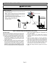
IMPORTANT
Only use Allen wrenches of sufficient hardness (50Rc −
Rockwell Harness Scale minimum). Fully insert the
wrench into the valve stem recess.
Service valve stems are factory−torqued (from 9 ft−lbs for
small valves, to 25 ft−lbs for large valves) to prevent
refrigerant loss during shipping and handling. Using an
Allen wrench rated at less than 50Rc risks rounding or
breaking off the wrench, or stripping the valve stem
recess.
See the Lennox Service and Application Notes
Corp.0807−L5 (C−08−1) for further details and
information.
When servicing or repairing HVAC equipment and
components, ensure the fasteners are appropriately
tightened. Table 1 list torque values for various caps and
fasteners.
Table 1. Torque Requirements
Parts Recommended Torque
Service valve cap 8 ft.− lb. 11 NM
Sheet metal screws 16 in.− lb. 2 NM
Machine screws #10 28 in.− lb. 3 NM
Compressor bolts 90 in.− lb. 10 NM
Gauge port seal cap 8 ft.− lb. 11 NM


