


Page 26
Optimizing System Refrigerant Charge
This section provides instructions on optimizing the
system charge. This section includes:
S Optimizing procedure
S Adjusting indoor airflow
S Using subcooling method
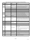
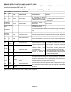
S Approved matched components, targeted subcooling
(SC) values and add charge values
S Normal operating pressures
S Temperature pressures
OPTIMIZING PROCEDURE
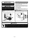
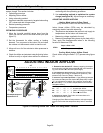
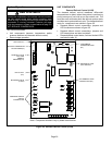
1. Move the low−side manifold gauge hose from the
vapor line service valve to the true suction port (see
figure 21).
2. Set the thermostat for either cooling or heating
demand. Turn on power to the indoor unit and close
the outdoor unit disconnect switch to start the unit.
3. Allow unit to run for five minutes to allow pressures to
stabilize.
4. Check the airflow as instructed under Adjusting Indoor
Airflow to verify or adjust indoor airflow for maximum
efficiency. Make any air flow adjustments before
continuing with the optimizing procedure.
5. Use subcooling method to optimize the system
charge (see figure 24). Adjust charge as necessary.
ADJUSTING INDOOR AIRFLOW
Heating Mode Indoor Airflow Check
(Only use when indoor unit has electric heat)
Indoor blower airflow (CFM) may be calculated by
energizing electric heat and measuring:
S Temperature rise between the return air and supply air
temperatures at the indoor coil blower unit,
S Measuring voltage supplied to the unit,
S Measuring amperage being drawn by the heat unit(s).
Then, apply the measurements taken in the following
formula to determine CFM:
CFM =
Amps x Volts x 3.41
1.08 x Temperature rise (F)
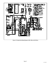
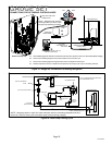
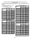
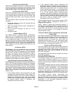
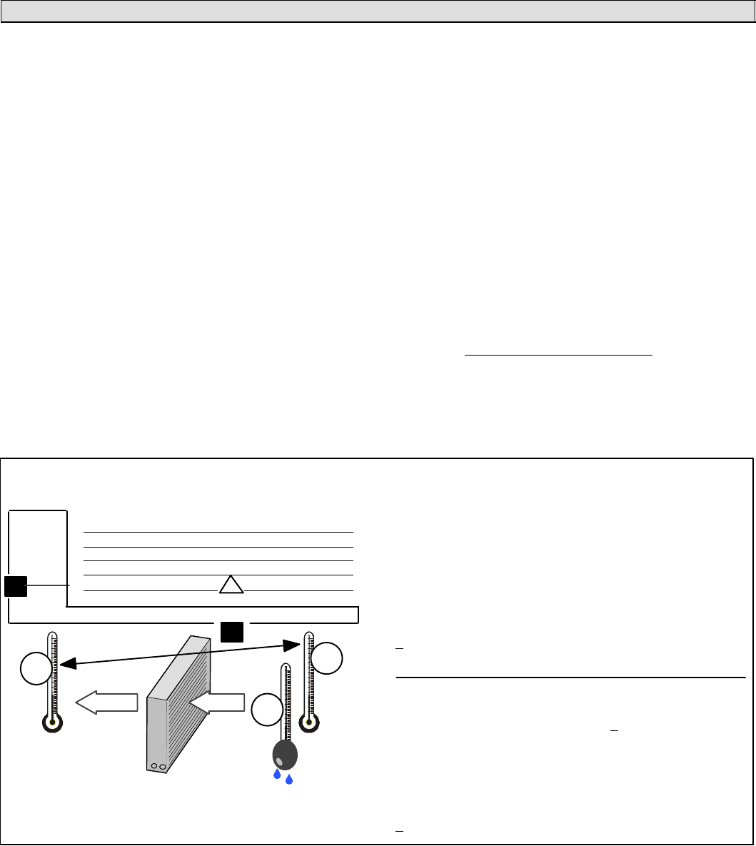
Cooling Mode Indoor Airflow Check
Check airflow using the Delta−T (DT) process using figure
23.
1. Determine the desired DTĊMeasure entering air temper-
ature using dry bulb (A) and wet bulb (B). DT is the intersect-
ing value of A and B in the table (see triangle).
2. Find temperature drop across coilĊMeasure the coil’s dry
bulb entering and leaving air temperatures (A and C). Tem-
perature Drop Formula: (T
Drop
) = A minus C.
3. Determine if fan needs adjustmentĊIf the difference between
the measured T
Drop
and the desired DT (T
Drop
–DT) is within
+
3º, no adjustment is needed. See examples: Assume DT =
15 and A temp. = 72º, these C temperatures would necessi-
tate stated actions:
Cº T
Drop
– DT = ºF ACTION
53º 19 – 15 = 4 Increase the airflow
58º 14 – 15 = −1 (within +3º range) no change
62º 10 – 15 = −5 Decrease the airflow
4. Adjust the fan speedĊSee indoor unit instructions to in-
crease/decrease fan speed.
Changing air flow affects all temperatures; recheck tempera-
tures to confirm that the temperature drop and DT are within
+
3º.
DT
80 24 24 24 23 23 22 22 22 20 19 18 17 16 15
78 23 23 23 22 22 21 21 20 19 18 17 16 15 14
76 22 22 22 21 21 20 19 19 18 17 16 15 14 13
74 21 21 21 20 19 19 18 17 16 16 15 14 13 12
72 20 20 19 18 17 17 16 15 15 14 13 12 11 10
70 19 19 18 18 17 17 16 15 15 14 13 12 11 10
57 58 59 60 61 62 63 64 65 66 67 68 69 70
Temp.
of air
entering
indoor
coil ºF
INDOOR
COIL
DRY
BULB
DRY
BULB
WET
BULB
B
T
Drop
19º
A
Dry−bulb
Wet−bulb ºF
A
72º
B
64º
C
53º
air flowair flow
All temperatures are
expressed in ºF
ADJUSTING INDOOR AIRFLOW
Figure 23. Checking Airflow over Indoor Coil Using Delta−T Formula