


Page 25
XP16 SERIES
TO LIQUID
LINE SERVICE
VALVE
TEMPERATURE SENSOR (USE FOR
SUBCOOLING METHOD)
DIGITAL SCALE
REFRIGERANT
TANK
TEMPERATURE SENSOR
(LIQUID LINE)
MANIFOLD GAUGE SET
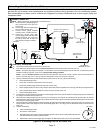
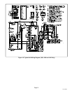
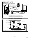
A Close manifold gauge set valves and connect the center hose to a cylinder of HFC−410A. Set for liquid phase charging.
B Connect the manifold gauge set’s low pressure side to the true suction port.
C Connect the manifold gauge set’s high pressure side to the liquid line service port.
D Position temperature sensor on liquid line near liquid line service port (use only for subcooling method).
OUTDOOR UNIT
CHARGE IN
LIQUID PHASE
CONNECTIONS FOR OPTIMIZING SYSTEM CHARGE
GAUGE SET
A
C
D
LOW
HIGH
B
INSIDE OUTDOOR UNIT
TRUE SUCTION PORT
CONNECTION
NOTE Ċ Refrigerant tank should be
turned right−side−up to deliver vapor
during charge optimizing procedure.
Figure 21. Gauge Set Connections for Adding Refrigerant
NOTE − Use gauge ports on vapor line valve and liquid valve for evacuating refrigerant lines and
indoor coil. Use true suction port to measure vapor pressure during charging.
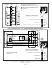
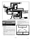
OUTDOOR
COIL
CHECK / EXPANSION
VALVE
BI−FLOW FILTER / DRIER
COMPRESSOR
REVERSING VALVE
MUFFLER
NOTE − ARROWS INDICATE DIRECTION
OF REFRIGERANT FLOW
SERVICE
PORT
VAPOR
CHECK / EXPANSION VALVE
INDOOR UNIT
OUTDOOR UNIT
LIQUID LINE
SERVICE PORT
DISTRIBUTOR
INDOOR
COIL
TRUE SUCTION
PORT
Figure 22. Heat Pump Cooling Cycle